
Figure 1.
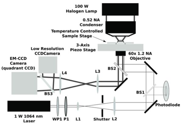
Optical setup including the optical trapping beam path and the bright field imaging. A half waveplate (WP1) and a polarizer (P1) form an attenuator for a 1 Watt, diode-pumped solid-state 1064 nm continuous-wave laser. Lenses L1 and L2 form a beam expander. A beamsplitter (BS1) provides a small amount of the beam to monitor the laser power. A dichroic mirror (BS2) directs the columnated beam into a 60x/1.2 NA water-immersion objective to form the optical trap in the sample. A tube lens (L3) forms an image on the EM-CCD (which can be used as either a high-speed camera or a quadrant detector).