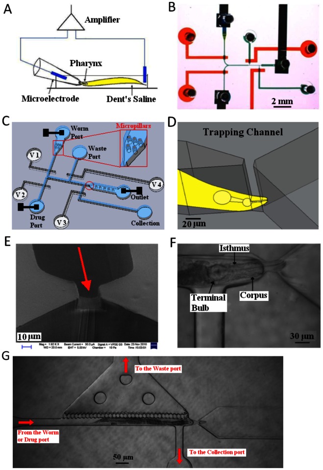
Figure 2. Conventional and microfluidic methods for extracellular electrophysiological recording from the C. elegans pharyngeal nervous system.
A. Schematic of conventional microelectrode EPG recording setup. B. Photograph of the microfluidic NeuroChip. Channels filled with food dye: Green flow layer; red control layer. C & D. Diagram of the NeuroChip. It is a two-layer structure: the blue layer is the microfluidic region processing worms and delivery of drugs. Trapping region (red circled) is magnified in D, showing the trapped worm’s head. The red square is the micro-pillar region which facilitates correct orientation of the worm. The white layer is the pneumatic control layer (V1, V2, V3 and V4 indicate Valve 1, 2, 3 and 4 respectively). The three black squares are the microelectrodes. E. SEM image of the trapping region. F. Photograph of a worm trapped in the device. The worm is trapped at the front part of its corpus. G. Addition of a wide perforated chamber alongside the worm to facilitate rapid drug access (see text for details).

