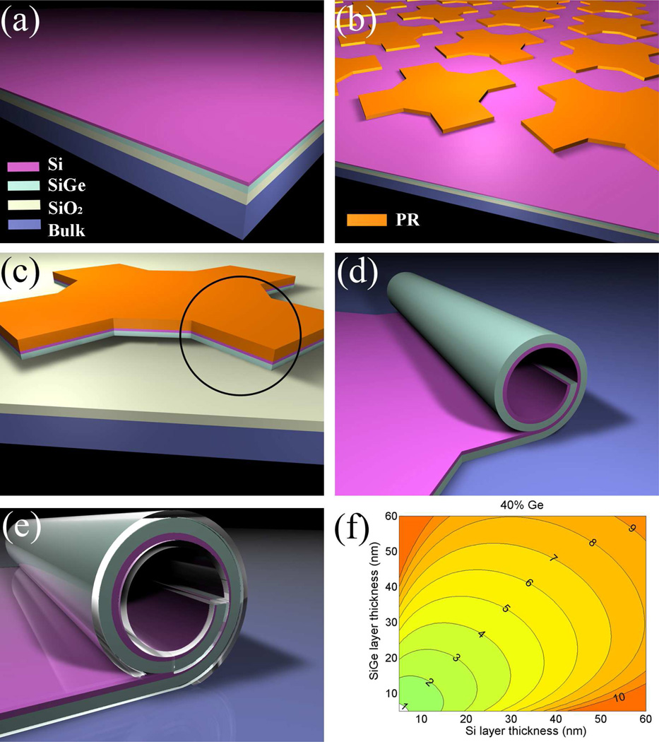
Figure 1.
Fabrication diagrams and contour plots of tube diameters. (a) The initial material, with Si epitaxially grown on SGOI; (b) arrays patterned by lithography, using photoresist (PR) as an etch-stop for the next step; (c) with a single pattern as an example, reactive-ion etching (RIE) to define the mesa (Note SiO2 survives this step because it has a very low etch rate); (d) after HF etching, the circled part from step (c) rolls up into a tube; (e) optional coating with biocompatible polymer to passivate the surface; (f) contour plot of how Si and SiGe layer thicknesses affect the tube diameter, at 40% of Ge concentration in the SiGe alloy. The values on the contours are tube diameters in µm.

