Figure 2.
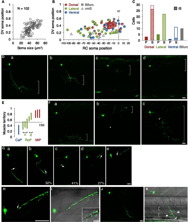
Single cell labeling of Gal4FF expressing cells in mnGFF7. (A) The plot of the single GFP-labeled motoneurons (open gray circles) with respect to the soma size on the horizontal axis and to the position of the soma along with the DV axis on the vertical axis. The DV soma position is normalized to the dorsal (y = 1) and the ventral (y = 0) edge of the spinal cord. (B) Distribution of the GFP-labeled cells plotted with respect to the soma position along the RC axis on the horizontal axis and to the DV soma position on the vertical axis. The exit point of the ventral root from the spinal cord is indicated on the RC axis by the gray vertical line marked as vr (x = 0). The dorsally, laterally and ventrally projecting cells are shown as red, green, and blue circles, respectively. The cells with bifurcating main axon and the vmS motoneurons are shown as gray squares and open triangles, respectively. (C) Cell counts of the neurons innervating the axial muscles based on the axon trajectory and muscle innervation pattern. P and S indicate primary and secondary motoneurons, respectively. Diagonally-striped bars indicate iS-type neurons. “Bifurc” indicates the motoneurons with a bifurcating main axon. (D) Primary motoneurons innervating ventrally (a), ventrolaterally (b), dorsolaterally (c), or dorsally (d). (E) Muscle innervation territory of the primary motoneurons. The position of the horizontal myoseptum (y = 0.5) is indicated as a gray horizontal bar. (F) Secondary motoneurons innervating ventrally (a, vS), dorsally (b, dS), or dorsoventrally (c, dvS). The arrowhead in (c) indicates the bifurcation in the main axon. The asterisk in (b) is the axon of another motoneuron in the opposite hemi-segment. (G) The secondary motoneuron innervating the ventral (a), ventrolateral (b), horizontal (c), dorsolateral (d), or dorsal (e) myoseptal region. The arrows indicate the axon terminals and roughly indicate their direction of extension. The percentiles show the ratio among the laterally projecting cells. (H) A cell innervating the dorsal myotseptum. The arrow indicates the axon terminal. This cell is identical to the one shown in (Ge) and the image was taken 6 h after the image (Ge) was taken. Note that the morphology of the soma changed dramatically in 6 h. (I) The superficial myoseptal region of (H) merged with the DIC image. The inset shows a stack of a few confocal sections indicated in the dotted square in (I). The axon collaterals cross the myoseptal boundary marked by the black dotted line. (J,K) A vmS-type neuron. The arrow and arrowheads indicate the axon terminal and the collaterals extending along the blood vessels, respectively. All images in (D–I) were taken during 72–100 hpf and the rostral is to the left. In (D,F,G,J), the oblique and horizontal dotted lines demarcate the myoseptal boundaries and the ventral edge of the spinal cord, respectively. The brackets roughly indicate the innervation territory along the dorsoventral axis in (D,F), and the axial blood vessels in (K). The bars indicate 20 μm, except in (I), where the bars indicate 10 μm.

