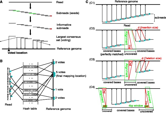
Figure 1.
Seed-and-vote mapping paradigm. (A) Schematic of the proposed mapping paradigm. Subreads (or seeds) are short continuous sequences extracted from each read. Substrings in green are uninformative subreads, and they are excluded from voting. Little red bars denote mismatched bases. Mapping location of the read is determined by the largest consensus set. The thin solid arrows point to the mapping location of each subread included in the largest consensus set. Mapping location of the read, as indicated by the black up-pointing triangle, is voted for by all the subreads in the largest consensus set. The dashed arrows indicate other mapping locations for the subreads, and these locations were disregarded due to insufficient number of votes. (B) Using an artificial example to illustrate the paradigm. Six subreads are extracted from the artificial read. Each square bracket denotes an extracted subread, which contains five continuous bases, and the number embedded in the blue cycle indicates the subread number. Base sequence of each subread is encoded into a string of 0’s and 1’s (each base is encoded into a 2-bit binary number). Encoded value for each subread is used as its key in the hash table. The key’s value gives the chromosomal location/s in the genome to which the corresponding subread is perfectly matched (no mismatches allowed). Four candidate mapping locations are found for this artificial read, which receive 2, 5, 1 and 2 votes (number of consensus subreads), respectively. The location that receives the largest number of votes, in this case the location with five votes, is selected as the final mapping location for this artificial read. (C) Indel detection performed under the seed-and-vote paradigm. (C1) shows the mapping results of subreads when there are no indels found in the reads (assuming no mismatches exist in the read for simplicity). (C2) and (C3) show respectively the schematic for detecting an insertion (Ins) and a deletion (Del) in the situation where insertion or deletion is found in the read and flanking subreads are found at both sides of insertion or deletion. (C4) gives the schematic for detecting indels when they occur at the locations close to the end of the reads where flanking subreads can be found at only one side. In (C2) and (C3), chromosomal locations pointed to by red arrows are the true mapping locations of subreads 8, 9 and 10, respectively, and chromosomal locations pointed to by dotted black arrows indicate the chromosomal locations to which they will be mapped if no indels exist before them. d is the indel length, equal to the difference between the location pointed to by the red arrow and the location pointed to by the dotted black arrow from the same subread. Regions encompassed by the dotted green lines are found to contain indels [(C2) and (C3)] or are candidate regions for searching indels (C4). Bases in these regions are not covered by subreads that have made successful votes, and their mapping locations will be determined by aligning to the corresponding regions (within the dotted green lines) in the reference genome. In (C4), a 4 bp window is moved along the uncovered bases to look for potential indels. When three or more bases in the window are found to be mismatches, the indel detection process is triggered for the search of indels.

