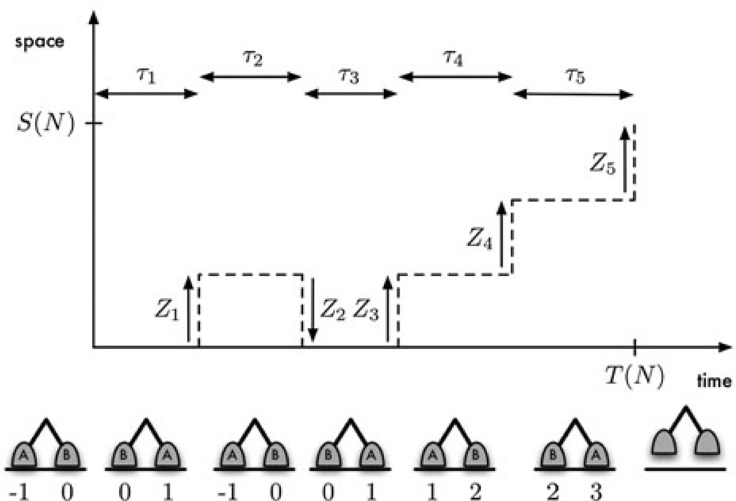
Figure 2.
A diagrammatic representation of processivity. The motor depicted took five steps (N = 5) before dissociating at time . Steps 1, 3, 4, and 5 were forward steps (Z1 = Z3 = Z4 = Z5 = 1), and step 2 was backward (Z2 = −1). Hence the displacement at dissociation was S(N) = 3. The figure below each dwell shows the position of the motor’s two heads at the end of the dwell. The location of the front head at time 0 is taken to be 0.

