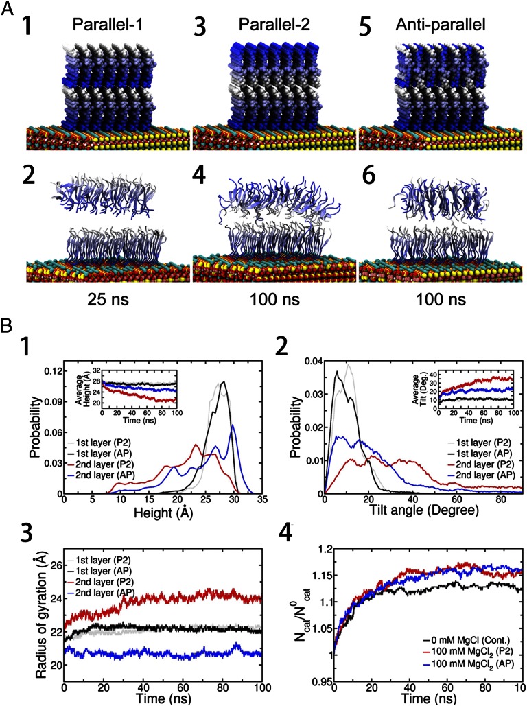
Fig. 4.
(A) Representative structures from molecular dynamics simulation. Three different models, the P1, P2, and AP models, were configured. The blue gradient is diminished from the N-terminus to C-terminus of the peptide. In all three models, the 7 × 7 peptides in the sublayer are configured in parallel on the mica surface (Fig. S3) and the positive N-terminal NH3+ ions are compensated for by a corresponding number of Cl− ions in the initial structure. Then, the whole system is immersed in 100 mM MgCl2 explicit water solution. (A1) In the P1 model, the 7 × 7 GAV-9 peptides in the top layer are configured in parallel with their N termini touching C termini of the sublayer. (A2) P1 model after 25 ns. (A3) In the P2 model, the 7 × 7 GAV- 9 peptides in the top layer are configured in parallel. In contrast to the P1 model, the C termini touch the C termini of the sublayer. (A4) P2 model after 100 ns. (A5) In the AP model, the 7 × 7 GAV-9 peptides in the top layer are configured antiparallel. (A6) AP model after 100 ns. Average heights (B1), tilting angles (B2), Rgs (B3), and excess cation density on mica surface (B4) of the peptide assemblies. Cont., control system; Deg., degree; Ncat, number of adsorbed cations (K+ or Mg2+) on the mica surface at a given moment; N0cat, number of stoichiometric cations (only K+ ) that neutralize the mica surface after GAV-9 peptides are adsorbed on it. Simulations start with randomly distributed K+ ions, which are detached from the mica surface due to GAV-9 adsorption.

