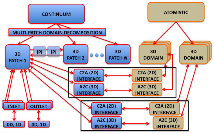
Figure 6.
A schematic representation of task parallelism in our coupled solver. The continuum domain is partitioned into N overlapping patches ΩCi, and the patches exchange data via inter-patch communicators. Each ΩCi has multiple inlets and outlets, and each patch may be connected to 0D or 1D arterial network model in order to model BCs for inlets/outlets. Two atomistic domains ΩAi are placed inside ΩC1. Each ΩAi can be replicated several times to reduce statistical error. Each ΩAi is linked to a ΩC1via two interfaces: A 2D interface which considers the boundaries of ΩAi and uses data computed in ΩCi as BCs. A 3D interface, which is tailored to the immersed boundary method; ΩC1 uses an external force field computed in ΩAi.

