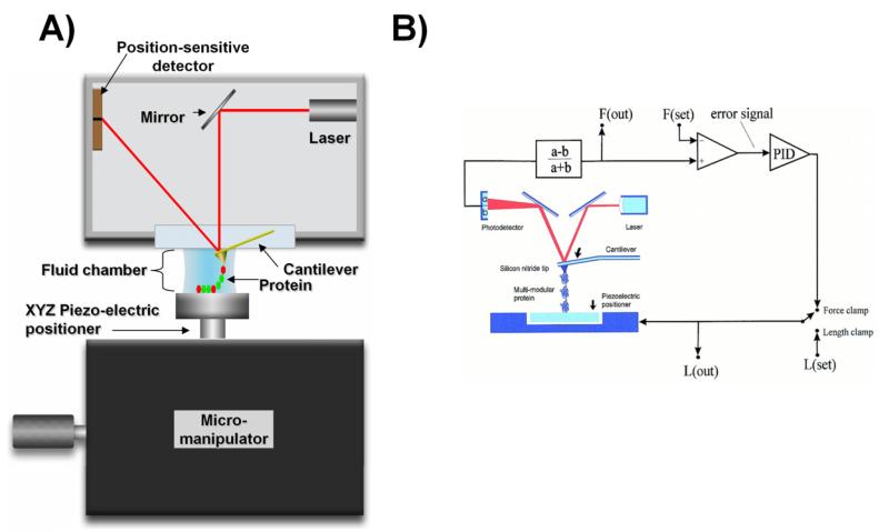
Figure 1. Schematic diagram of the AFM apparatus and associated control electronics.
A) The AFM consists of two main parts: the scanner (Micromanipulator) and an optical head. The center point of the system is a small cantilever that functions as a microscopic spring. The cantilever is brought into contact with the sample and its bending is detected by shining a laser on its back; the light bounces off and is captured by a split photodetector (split into two regions: ‘a’ and ‘b ’photo-signals). A tiny deformation of a few nanometers causes a large alteration in the photovoltage of the detector due to optical amplification of the signal. The photovoltage is then converted into a force signal. The AFM is very sensitive it can measure forces in the range of pico-newtons and distances of only few angstroms. B) Two modes can be used to stretch single molecule: length-clamp or force-clamp modes. The standard length-clamp mode allows the control of the position (L) and measurement of the resulting force (F) which is calculated from the laser deflection (a − b)/(a + b). The force-clamp mode measures force and then compare it with a set value thus generating an error signal that is fed to a proportional, integral and differential amplifier (PID) whose output is connected directly to the piezoelectric positioner. Reproduced with permission from (84).

