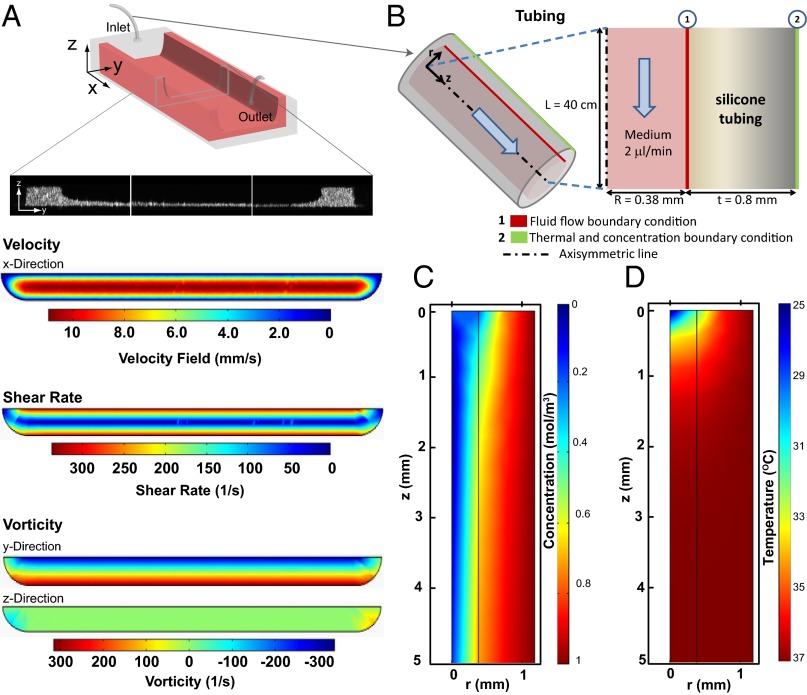
Fig. 2.
Computational modeling of flow in the microfluidic platform. (A) Schematics of the cross-section of microchannels with a stromal bed (Matrigel coating). (Top to Bottom) Velocity field (mm/s), shear rate (1/s), and y- and z- components of vorticity distribution (1/s) are plotted across the cross-section above the Matrigel. (B) Schematic for gaseous and thermal equilibration across porous tubing. The length of the tube inside the incubator was designed to be sufficiently long to allow gaseous and thermal equilibration before entry of the medium into microchannels. (C) CO2 concentration (moles/m3) and (D) Temperature (°C) contours on the axisymmetric layer of medium and porous tubing that feeds the microchannel with culture medium that is sufficiently equilibrated to the appropriate temperature and CO2 levels before entering the channel.

