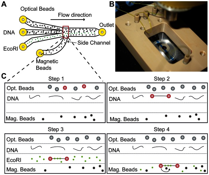
Figure 3. Step by step assembly of DNA tethers using a laminar flow system.
(A) Schematic of the laminar flow cell showing four different inlets, that are combined into a central channel. Magnetic beads are flushed in via a side channel that exits perpendicular to the main flow direction. This allows for a very low flow rate (<10 µL/h) during experiments, while preventing diffusion into this channel. (B) Photograph of a flow cell using three channels, the central channel contains blue dye, showing clear separation by laminar flow from the other two flow lanes. (C) Illustration of the step-by-step assembly procedure to perform the scanning loop experiments. In step 1 two beads are caught by optical tweezers. In step 2 a biotin-labeled DNA molecule is tethered between the streptavidin-coated beads. In step 3 the presence of a single DNA molecule is confirmed by force extension analysis and EcoRI proteins are allowed to bind to the tethered DNA molecule. In step 4 the DNA tether is brought within close distance of a magnetic bead tether and a loop is formed. A low concentration of EcoRI proteins is present in this channel to assure that proteins remain bound to the DNA.

