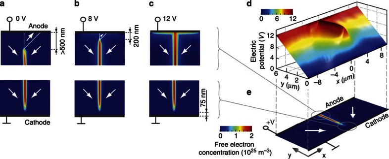
Figure 4. Connecting a charged domain wall and electrodes by an applied voltage.
(a–c) Colour-scale map of the phase field calculated free-electron concentration at a head-to-head domain wall when an electric potential is being applied. The wedge-like domain disconnects the free-electron gas from the anode when the potential difference is below 8 V. The free-electron gas is permanently disconnected from the cathode. (d) Colour-scaled landscape of electric potential in the vicinity of the domain wall when 12 V is applied. The charged domain wall is at equipotential with the anode. (e) Illustration of the polarization (arrows) and free-charge (color-scale) distribution under the applied 12 V.

