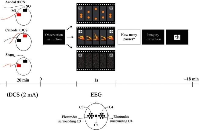
Figure 1.
Experimental Design. The order of observation videos was random and always followed by the imagery correspondent condition. The surrounding electrodes are: surround C3 (EGI electrodes: 29, 30, 35, 37, 41, 42), Cz, surround C4 (EGI electrodes: 87, 93, 103, 105, 110, 111). The sound symbols represent the moment when the metronome stimulus occurs pacing each cycle. For tDCS conditions red represents the anode and black represents cathode. SO represents the supraorbital (reference) area.

