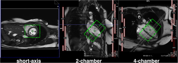
Figure 41.

Frequency and shim adjustment box. Example of the positioning of the frequency and shim adjustment volume (represented by the green box) shown in three anatomical slices. The dashed rectangle represents the position of the short-axis slices being acquired. The appearance and application of this will vary between manufacturers.
