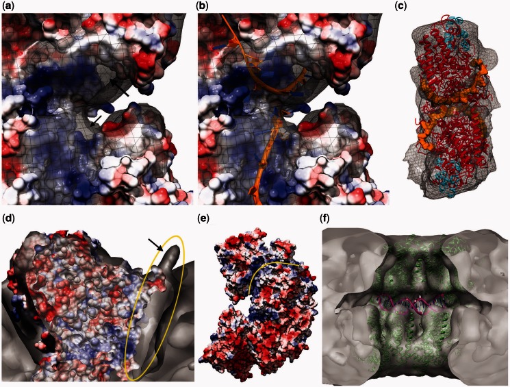
Figure 4.
Proposed locations of DNA in the oligomeric ring structure. (a) It shows a side view of the putative ssDNA-binding sites of a top and bottom monomer pair fitted into one symmetrical unit (i.e. close-up side view of the ssDNA-binding surfaces shown in Supplementary Figure S6c) superimposed with the reconstructed map showing the extra density left unfilled after fitting. This is visible around the positively charged surface shown in blue (arrows point to parts of these densities visible from this angle). (b) It shows the ssDNAs (rendered as orange ribbons) modeled as published previously (28), fitting into the extra density seen in a. (c) It shows an isolated symmetrical unit with the fitted PDB (red and cyan for N- and C-termini, respectively) and the modeled ssDNAs bound to the top and bottom monomers (rendered orange, space filling). The view point corresponds to the side that faces to the center of the ring. (d) It is a clipped top view rendering showing the extra density (circled yellow) left unfilled around the positively charged (blue) surface after fitting the crystal structure. This unfilled density extends to the outside of the ring, creating a small protrusion (arrow). (e) It shows the side view surface-charge representation of two monomers fitted into one symmetrical unit. The positively charged path (blue) on the top monomer (marked by a yellow line) coincides with the extra density shown in d. This positively charged path starts from the proposed ssDNA-binding site (facing left here, shown in a as a close-up from the other side) and extends all the way to the outside of the monomer, coinciding with the small protrusion shown in d. Hence, this extra density is suggested to represent the DNA entering into or exiting from the oligomeric ring through a port formed between two monomers placed next to each other. (f) It shows the PatchDock result obtained by docking a bent 20-bp dsDNA molecule (see ‘Materials and Methods’ section) to a fitted ICP8 tetramer composed of two symmetrical units.

