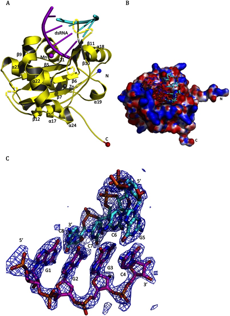
FIGURE 2.
Crystal structure of the active RNase domain of LASV NP in complex with the 5′-ppp dsRNA oligo. A, in the LASV NP-C·dsRNA complex structure, LASV NP-C is shown in yellow for the backbone, with a blue ball indicating the N terminus and a red ball indicating the C terminus, whereas the dsRNA substrate is shown in magenta for the cleaving strand and in cyan for the complementary strand. Positions of the α-helices and β-sheets are indicated. A Mn2+ ion is shown as a magenta ball and a zinc ion as a gray ball. B, electrostatic surface potential map of the LASV NP-C domain in complex with the dsRNA substrate (shown in a stick model). Red and blue indicate negatively and positively charged surface potentials, respectively. C, the Fo − Fc electron density map contoured at 2.5 σ is shown in blue mesh for the dsRNA substrate. The dsRNA is shown in stick with the cleaving strand in magenta and the complementary strand in cyan.

