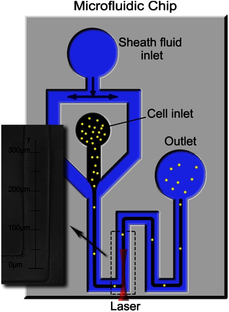
Fig. 2.
Layout of the microfluidic channel design: two inlets and one outlet were punched using Harris Uni-Cores with different diameters (7 and 5 mm). The weakly focused laser beam was propagated along the flow direction. The laser-guidance region, outlined with a dashed box, is where the addition of optical force caused the cells to increase their flow speed.

