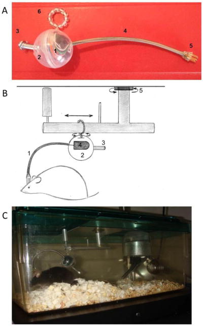
Fig 1.

Photograph and schematic of the components of the new system and a photograph of a mouse using the new system to measure biopotentials. (A) (1) Telemetry transponder. (2) Container encapsulating the telemetry transponder. (3). Weighted counterbalance. (4) Flexible protective sheath containing the wires from the telemetry transponder. (5) Pins connecting the wires from the transponder to the EEG/EMG electrodes on the head of mouse. (6) O-ring holding the aforementioned components that rotates 360 degrees and slides on a metallic bar. Thus, this apparatus minimizes the weighted pressure of the cable on the animal and does not restrict mobility. (B) The mouse head cap containing EEG/EMG electrodes is connected to a telemetry transponder (4) encapsulated in a protective covering (2) by short cables contained in a lightweight protective sheath (1). This system is counterbalanced (3), rotates on an O-ring that swivels 360 degrees and slides horizontally between two contained ends, and possesses an additional swivel allowing the maximal range of movement within the mouse housing (5). (C) Photograph of a mouse using the new system.
