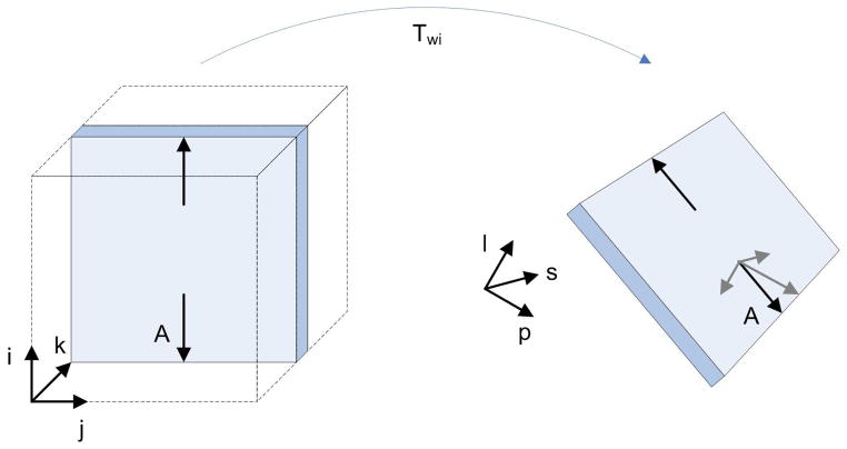
Figure 10.
Distortions in WC. At left, a magnification in the phase encoding direction is represented by arrows parallel to i (arrows are much longer than in real cases for representation purposes). After transforming the slice into WC, the arrow A has components along each one of the directions defining the WC system (l = left, p = posterior, s = superior). Therefore, a magnification along a single direction in IC becomes a magnification along all directions in WC. The same concept is applicable to shearing and translation.

