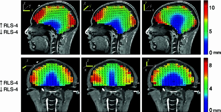
Fig. 12.

Equivalent dipole source localization error directions (arrows) and magnitudes (colors) in a four-layer reference BEM head model when the co-registered scalp electrode positions were tilted 5° backwards (top row), or 5° to the left (bottom row) before dipole localization. White arrows in the left most panels show the approximate size of the simulated co-registration error. Other details as in Fig. 3
