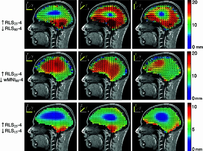
Fig. 13.

Equivalent dipole source localization error directions (arrows) and magnitudes (colors) for model dipoles in a four-layer realistic BEM head model when the brain-to-skull conductivity ratio was mis-estimated as 80:1 (top row) or as 15:1 (bottom row) instead of the simulated forward-model value (25:1). The middle row shows errors when source localization was performed using a warped four-layer MNI head model and the forward model brain-to-skull ratio was again mis-estimated as 80:1. Note that, maximum error shown was 20 mm for top and bottom rows so as to use the same scaling while retaining some contrast for the lower-error plots. Maximum localization errors were given in Table 3. Other details as in Fig. 3
