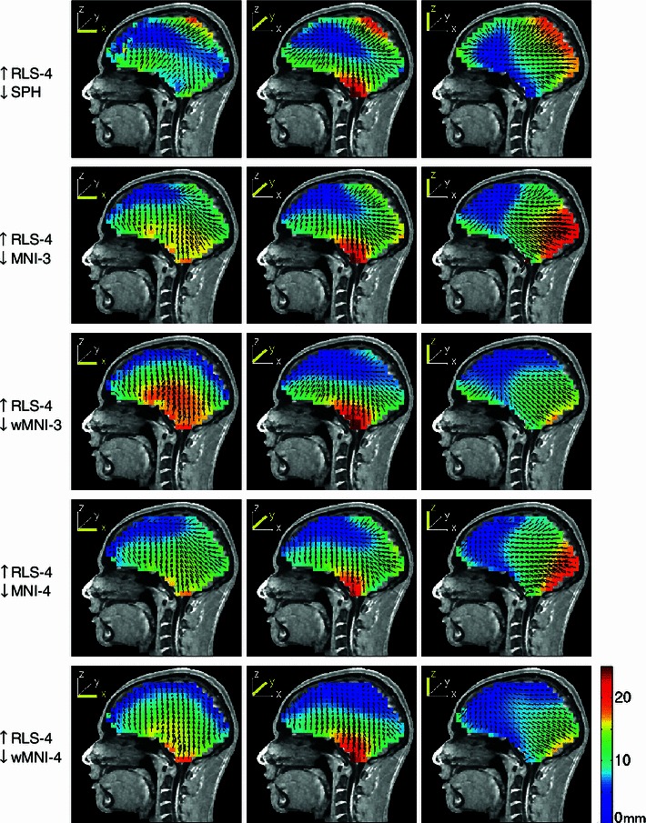
Fig. 4.

Equivalent dipole source localization error directions (arrows) and magnitudes (colors) for spherical (top row) and four MNI-template based head models computed from source dipole scalp projections computed using a four-layer realistic subject MR image based BEM forward head model (subject S1 in Fig. 2). The forward and inverse models are indicated to the left of each row (up arrow forward model, down arrow inverse model). The source space was a regular Cartesian grid of single current dipole sources with 8-mm spacing filling the brain volume. The three columns show the errors for equivalent dipole sources that were oriented in x, y, and z directions, respectively (see insets). Note that, maximum error shown was 25 mm so as to use the same scaling for all the plots while retaining some contrast for the lower-error plots. Maximum localization errors were given in Table 3
