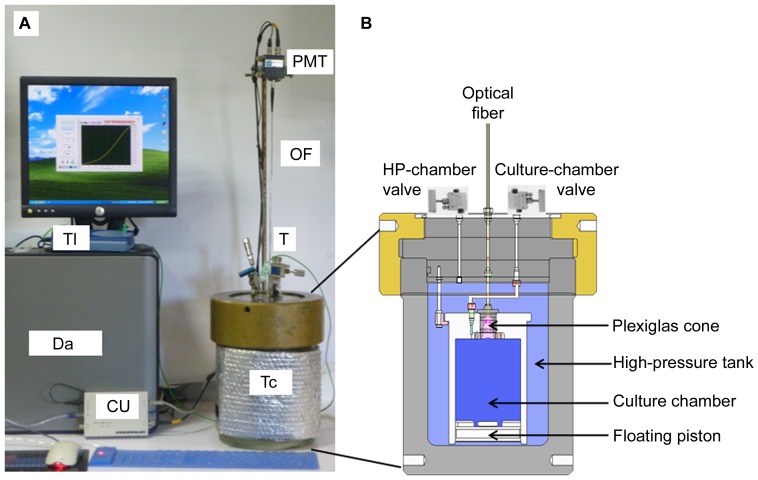
Figure 1. High-pressure bioluminescence system.
(A) Photography of the high-pressure bioluminescence system and (B) schematic section diagram of the high-pressure bioluminescence tank. PMT: photomultiplier tube; OF: optical fiber; CU: photomultiplier counting unit; T: high-pressure temperature sensor; Tc: Tubing around tank for temperature control connected to a thermo chiller (not shown); Tl: Data logger for temperature sensor; Da: PC for data acquisition of bioluminescence and temperature;

