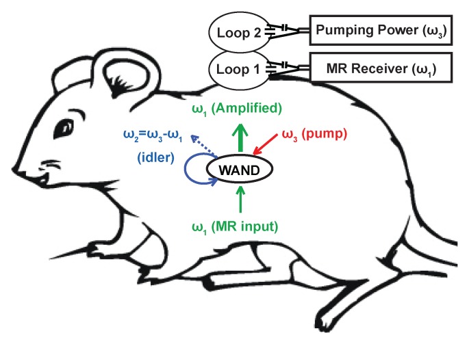
Figure 1a:
(a) WAND device implanted within an animal couples inductively to two external loops (Loop 1 and Loop 2). Loop 2 couples power via the pumping signal to the WAND at ω3 to convert the weak MR signal at ω1 into an amplified output at the idler frequency ω2. The idler current at ω2 mixes again with the pumping signal at ω3 to amplify the current at ω1, which couples out to loop 1 connected to the MR imaging system. (b) Schematic of the WAND implemented as a double resonant circuit coupled inductively to the external loops. (c) Photograph of the PDMS-encapsulated WAND device (see text for discussion of L1, C1, L2, and C2). (d) The phantom test arrangement with the WAND device placed on the surface of a 1% agarose gel. Loop 1 and loop 2 are both 22 mm in diameter and are mounted concentrically above the gel.

