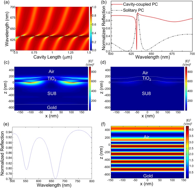
Figure 2.
RCWA simulated data for one period of the PC. (a) Far-field reflection of the cavity-coupled PC for various cavity lengths. The incidence angle is θ = 0°, which corresponds to the resonance angle of the PC. (b) Far-field reflection spectrum for one cavity length (740 nm) showing the coupling compared to that of the solitary PC. (c) and (d) Near-field electric field intensity distribution for the cavity-coupled PC and the solitary PC at the resonance wavelength showing enhanced fields for the case of the coupled modes. (e) Far-field reflection spectrum for the un-corrugated structure for one cavity length (740 nm). (f) Near-field electric field intensity distribution for the un-corrugated structure at the reflection dip corresponding to λ ∼ 660 nm.

