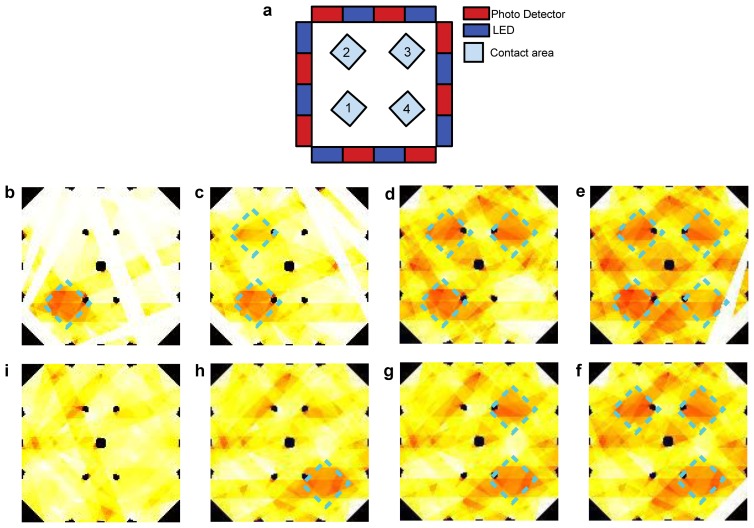
Figure 17.
(a) Design layout of the sensor with the position of 4 subsequent and multiple contacts depicted. At bottom and clockwise: (b–e) show the corresponding two dimensional intensity profile obtained through the reconstruction by mapping the pixels signals, in which the multiple contacts square shape, corresponding to the applied pressure profile, can be reconstructed by the e-skin, as well their different positions; (f–i) show the subsequent release of the square shape contacts as detected by the e-skin.

