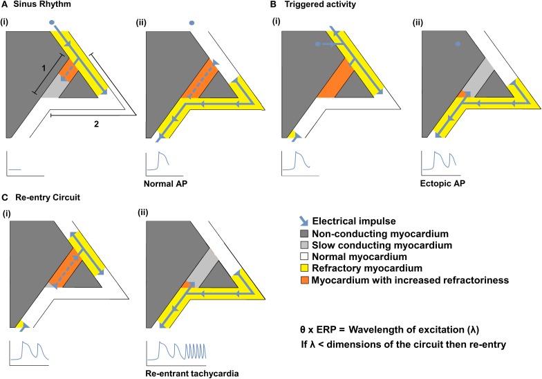
Figure 1.
The relationships between θ and re-entrant arrhythmia. A diagram illustrating a typical re-entry circuit, consisting of a pathway of slow conducting myocardium [A(i) path 1, light gray] passing through non-conducting myocardium (dark gray), bordered by a second pathway of normal myocardium [A(i) path 2, white]. (A) An electrical impulse (blue arrow) originating from the SAN, (i) propagates along path 2 (white) and path 1 (light gray) pathways. As the impulse conducts, the myocardium becomes refractory (yellow in path 2 or orange in path 1) (ii) The impulse that travels along path 2 reaches the end of the circuit resulting in a normal AP. The impulse that conducts along 1 cannot exit the circuit as it collides with the refractory tissue of path 2. (B) An abnormal impulse originating from an ectopic focus is triggered immediately following the sinus impulse (i). It cannot conduct down path 1 which remains refractory; it therefore conducts along path 2. (ii) When the impulse reaches the distal end of path 2 it splits, conducting retrogradely along path 1 and orthogradely along path 2. (C) The impulse conducting retrogradely along path 1 then activates the beginning of path 2 (i) without the need of any further stimuli, thereby creating a self-perpetuating re-entrant rhythm (ii). Such re-entry is more likely to occur following reductions in conduction velocity (θ) and/or the effective refractory period (ERP) that reduce the wavelength of excitation (λ), given by the product of the θ and ERP, to values smaller than the dimensions of the available circuits.

