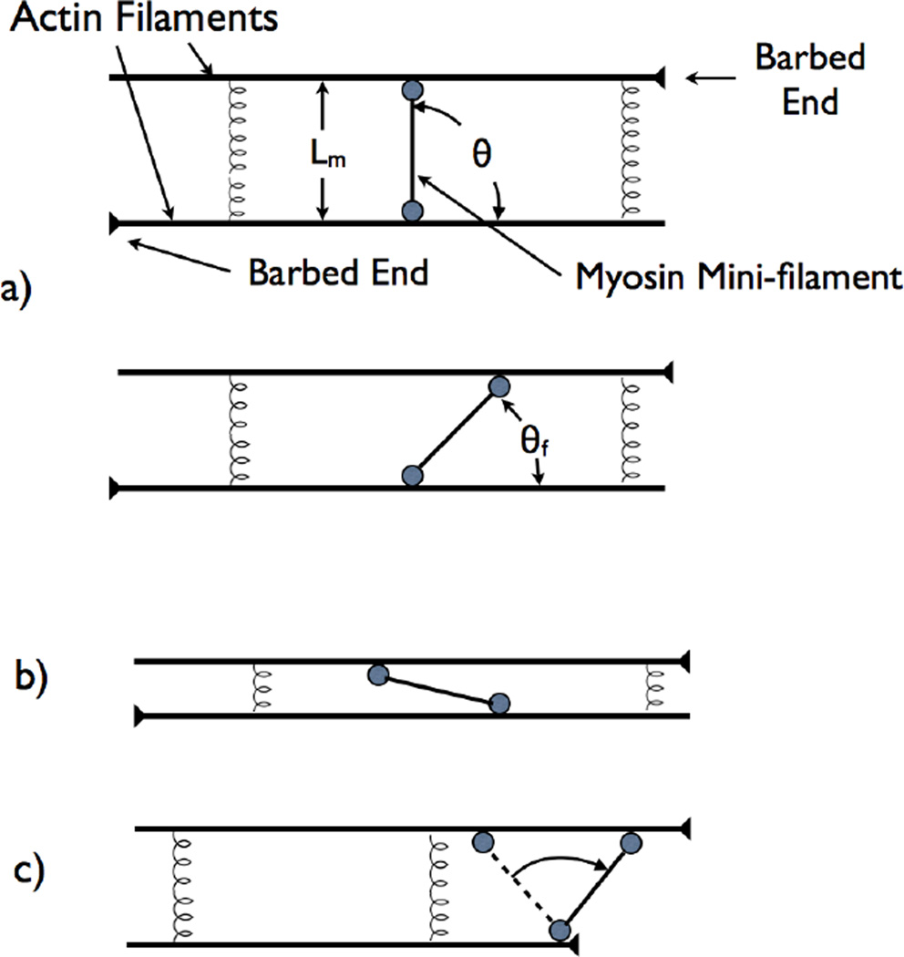
Figure 3.
Schematic of mini-filament rotation mechanism leading to contractile stress. a) Initial configuration with mini-filament perpendicular to two antiparallel filaments. b) Final configuration where mini-filament has rotated. c) Initial configuration where mini-filament is nearly parallel to actin filaments. d) Rotation mechanism when one mini-filament head stops at an actin filament barbed end.

