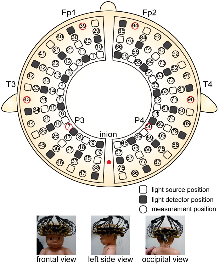
Figure 1. Arrangement of measurement positions.
The lowest lines of the probes correspond to the T3-Fp1-Fp2-T4 line according to International 10–20 electrode system. The vertical midline of the channels was centered in the nasion–inion line, and the channels between the 5th and 6th probe in the lowest line corresponded to T3 on the left and T4 on the right.

