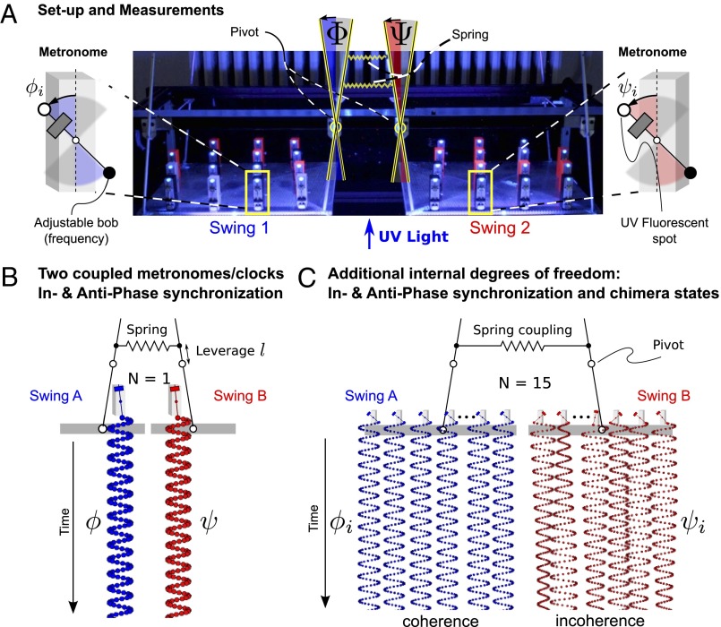
Fig. 1.
Experimental setup and measurements. Two swings are loaded with N metronomes each and coupled with adjustable springs. (A) Swing and metronome displacements are measured by digital tracking of UV fluorescent spots placed on the pendula and swings. (B)  Metronomes synchronize in AP or IP motion. (C)
  Symmetry-breaking chimera states with one metronome population synchronized and the other desynchronized, or vice versa. The displacement angles of the pendula on the left and right swings are
  and
and  , respectively.

