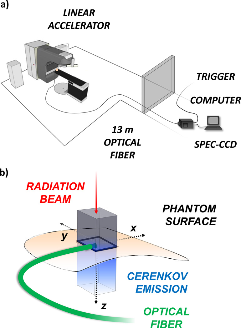
Fig. 1.
(color online) In (a) the experimental setup is shown with the computer controlled spectrometer-CCD system located outside of the treatment room, and light collected through a 13 m long optical fiber. The trigger was obtained from the LINAC external control unit. In (b) a schematic of Cerenkov emission in a phantom is illustrated. The radiation beam travels downward with a rectangular cross-section producing a column of Cerenkov emission below the surface. The optical fiber is placed on the phantom surface with the tip in the center of the radiation beam.

