
Figure 6.
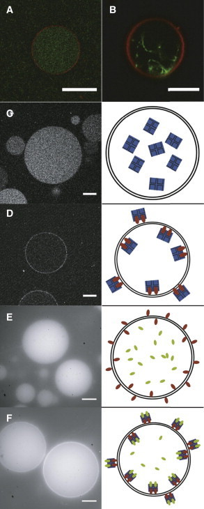
CLSM images of DOPC-GUVs grown by (A and B) PVA swelling at 4°C from 94.8:0.2:5.0 DOPC/RhodB-PE/PEG-PE mixtures and (C–F) DOPC-GUVs grown by a combination of PVA swelling and the inverse-phase precursor method (42). (A) Encapsulated actin filaments in the interior of the GUV. (B) Actin bundles inside the GUV, formed by adding of streptavidin with an actin/streptavidin ratio of 25:1 as a cross-linker. (C) In the absence of biotinylated lipids, AlexaFluor350-labeled neutravidin is homogeneously distributed in the vesicle interior. (D) In the presence of 1% biotinylated lipids, AlexaFluor350-labeled neutravidin binds to the membrane. (E) In vesicles swollen in a solution containing 500 nM fluorescently labeled biotin, the biotin is homogeneously distributed inside the vesicle interior in the absence of membrane-bound neutravidin. (F) Vesicles were formed as in (E) but with neutravidin on the membrane surface. The encapsulated biotin-fluorescein binds to the membrane-anchored neutravidin, resulting in a bright ring of fluorescent-biotin. The right column displays sketches of the systems in the left images: The membrane is represented by black lines, biotinylated lipids by red rods, fluorescein-biotin by green rods, and neutravidin by a blue square. Scale bars 20 μm.