Abstract
The chemical vapor deposition (CVD) fabrication of high-density three-dimension graphene macroscopic objects (3D-GMOs) with a relatively low porosity has not yet been realized, although they are desirable for applications in which high mechanical and electrical properties are required. Here, we explore a method to rapidly prepare the high-density 3D-GMOs using nickel chloride hexahydrate (NiCl2·6H2O) as a catalyst precursor by CVD process at atmospheric pressure. Further, the free-standing 3D-GMOs are employed as electrolytic electrodes to remove various heavy metal ions. The robust 3D structure, high conductivity (~12 S/cm) and large specific surface area (~560 m2/g) enable ultra-high electrical adsorption capacities (Cd2+ ~ 434 mg/g, Pb2+ ~ 882 mg/g, Ni2+ ~ 1,683 mg/g, Cu2+ ~ 3,820 mg/g) from aqueous solutions and fast desorption. The current work has significance in the studies of both the fabrication of high-density 3D-GMOs and the removal of heavy metal ions.
Graphene, a single graphite layer, has attracted huge interests for its remarkable properties such as large specific surface area, high electrical conductivity and great stiffness1. Among all the routes to synthesize graphene, chemically reduced graphene oxide and chemical vapor deposition (CVD) are widely considered to be the most promising ways for the mass production of graphene2,3. Even though the chemically reduced graphene oxide is potentially used in many research fields, such as energy storage devices, sensors, composites4,5,6,7,8,9,10, its preparation always brings about lots of defects and non-carbon functional groups on graphene sheets which seriously damage the electrical and mechanical properties of the intrinsic graphene11. So far, CVD method is extensively applied for growing large-area and high-quality graphene films on metal catalyst substrates12,13,14, whereas it produces graphene layers at the small quantities.
Three-dimension (3D) graphene made by CVD has recently raised increasing attentions due to its unique 3D porous structure, excellent physical properties and potential applications. Cheng group innovatively synthesized 3D graphene on nickel (Ni) foam catalysts by CVD, which shows the good mechanical and electrical properties of 3D graphene composites15. Since then, the passion for researches on the preparation of high-quality 3D graphene and its composites, as well as their potential applications has been continuous16,17,18,19,20,21,22,23. However, most of the works focus on Ni foam-based 3D graphene and their composites18,19,20,21. Though the preparation process is simple, these graphene foams suffer from the issues of large porosity (≥95%) and low density due to the limitation of the Ni foam catalyst skeletons. The Ni foam-based method is beneficial to the preparation of lightweight graphene materials, but it is limited in the yield and the mechanical strength required in some realistic applications. Therefore, it is necessary to explore the preparations and applications of high-density 3D graphene with smaller porosities. Meanwhile, a few groups have explored the growth of 3D graphene on Ni particle catalysts using polymers as solid carbon sources under low pressure. However, these processes are very time consuming and under low pressure due to possibly low catalytic reactivity and low gas penetration22,23. Therefore, these methods are unrealistic to form 3D graphene macroscopic objects (3D-GMOs) and it is significant to exploit a technique to rapidly obtain high-density 3D-GMOs for the promising applications.
Heavy metal ions such as cadmium (Cd), copper (Cu), lead (Pb) and Ni ions in industrial wastewater are harmful for organisms when they exceed tolerance values. They are not biodegradable and will accumulate readily in body, which causes ecological disequilibrium and health hazards. Thus efficient removal of heavy metal ions from industrial effluents is significant in water treatment. Active carbon has been widely studied in adsorption of heavy metal ions for their large specific surface area and micro porous structure24,25,26,27. Recently, graphene and graphene-based composites have also been reported in the adsorption of heavy metal ions28,29,30,31,32,33,34,35,36,37,38,39,40,41,42,43,44,45. Nevertheless, it usually takes hours to days to adsorb heavy metal ions by physical process. In addition, the adsorption capacity is low and the recovery process is much inconvenient. Therefore, it is a very meaningful exploration to find new materials and methods for the efficient adsorption and desorption of heavy metal ions. The 3D graphene prepared by CVD method is an ideal candidate of the electrodes for the electrolytic deposition for its large specific surface area, porous structure and excellent electrical conductivity. However, the fabrication of high-density 3D-GMOs and their speedy capture of heavy metal ions with high capacity have not yet been demonstrated.
Herein, we develop a rapid CVD synthesis of high-density 3D-GMOs grown on 3D porous cross-linked Ni skeleton catalysts fabricated by the reduction of nickel chloride hexahydrate (NiCl2·6H2O) crystalline. It takes relatively short time of several seconds to minutes in the growth process. As electrolytic electrodes, the 3D-GMOs exhibit the remarkable performance of the speedy capture of heavy metal ions with high capacity and the fast desorption.
Results
Fabrication of 3D-GMOs
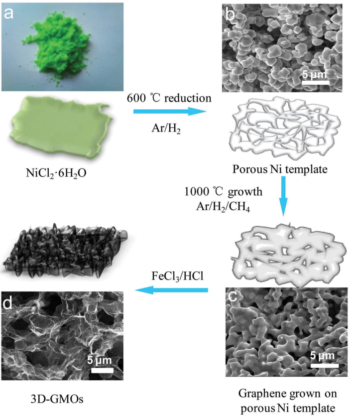
The growth process of our 3D-GMOs is illustrated in Figure 1, and NiCl2·6H2O is used as the catalyst precursor of porous Ni skeleton (Fig. 1a). Firstly, the precursors are reduced to form 3D porous cross-linked Ni skeletons in Ar/H2 atmosphere at 600°C (Fig. 1b). Next, the highly efficient growth is performed using methane as carbon source for only several seconds to minutes. Upon high-temperature annealing in the growth process, the tightly cross-linked catalyst skeletons with larger grain size are formed since the adjacent catalyst metals melted to come into being larger size at higher temperature (Fig. 1c). In contrast to the reported methods22,23, the advantages of our method to prepare 3D-GMOs lie in its fast growth process as well as its availability at atmospheric pressure. The effective growth is attributed to better catalytic reactivity and possibly high gas penetration through the porous 3D cross-linked Ni skeletons formed by the released gas (water vapor and hydrogen chloride) and melted metal at high temperature. Finally, the 3D-GMOs are obtained by removing Ni skeletons with FeCl3/HCl solution as etchant and followed by repeated water washes and freezing dry (Fig. 1d).
Figure 1. Schematic illustrations displaying the preparation process of 3D-GMOs.
(a) A photograph of green NiCl2·6H2O crystal precursors. (b) SEM image of porous cross-linked Ni catalysts after the reduction process. (c) SEM image of tightly cross-linked Ni catalysts covered by graphene layers. (d) SEM image of honeycomb-like graphene layers of the 3D-GMOs after etching Ni catalysts with FeCl3/HCl solution.
Characterization of the free-standing 3D-GMOs
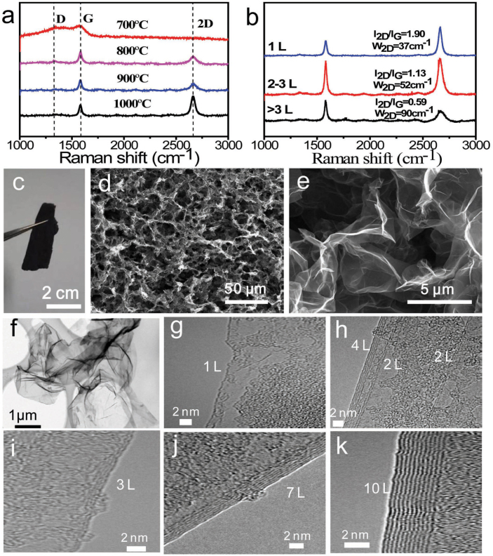
We investigate the effect of growth temperatures on the prepared 3D-GMOs within the temperatures from 700 to 1000°C for a fixed growth time of 1.5 min. Typical Raman spectra and scanning electron microscopy (SEM) images show that the quality of 3D-GMOs is gradually improved with increasing growth temperature (Fig. 2a and Supplementary Fig. S1). This can be attributed to the improvement of crystalline quality of polycrystalline Ni with increasing growth temperature, which is conductive to reduce defects and form the thinner graphene layers. The thin graphene layers of 3D-GMOs grown for 1.5 min at 1000°C are investigated by SEM, Raman spectroscopy, transmission electron microscopy (TEM) and atomic force microscopy (AFM). The free-standing 3D-GMOs show the honeycomb-like 3D interconnected morphology and curved graphene layers (Fig. 2c–e). The high conductivity (~12 S/cm) and the large specific surface area (~560 m2/g) are obtained by the two-probe method and the methylene blue adsorption, respectively. In addition, Figure 2b shows the typical Raman spectra of the 3D-GMOs. The number of graphene layers is estimated by 2D to G ratio (I2D/IG) together with 2D-band full-width at half maximum (FWHM, W2D)46, and it can be seen that monolayer, bilayer and multilayer graphene coexist in the 3D-GMOs. The non-uniformity of layers may derive from that the individual Ni grains with varying sizes in polycrystalline porous Ni skeletons independently affecting the thickness of graphene in the CVD process15. Furthermore, the weak defect-related D peak reflects the high quality of the graphene layers. TEM is further employed to investigate the number of the graphene layers of the prepared 3D-GMOs directly. Low-magnification TEM in Figure 2f shows the thin curved morphology of graphene layers. Figure 2g–k indicates that the layer numbers of most of the 3D-GMOs are less than 10 layers determined by high-resolution TEM. In addition, we confirm the thickness of the graphene layers by AFM. The step heights in the AFM images are typically less than 3 nm calculated from the height difference between the surface of the graphene layers and the SiO2 substrate, corresponding to the dominated range of graphene layer number of 1–7 L (Supplementary Fig. S2). Therefore, the layer thickness of the 3D-GMOs prepared by this strategy is conservatively estimated to be less than 4 nm.
Figure 2. Characterization the graphene layers of 3D-GMOs.
(a) Typical Raman spectra of 3D-GMOs grown with different temperatures for 1.5 min. The Raman spectra show that the quality of 3D-GMOs is gradually improved with increasing the growth temperature up to 1000°C. (b) Typical Raman spectra of a 3D-GMO. Multi-layer, bilayer and monolayer graphene from bottom to top estimated by the intensity ratio of 2D peak to G peak, combining with 2D-band full-width at half maximum (FWHM, W2D). (c) A photograph of the free-standing 3D-GMO. (d, e) SEM images of honeycomb-like graphene layers after etching Ni template with FeCl3/HCl solution at different magnifications. (f) Low-resolution TEM image of the graphene layers in a 3D-GMO. (g–k) High resolution TEM images of different graphene layers in a 3D-GMO. (g) Monolayer. (h) Double layers and four layers. (i) Three layers. (j) Seven layers. (k) Ten layers.
The high density of 3D-GMOs
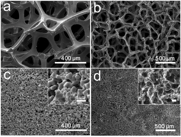
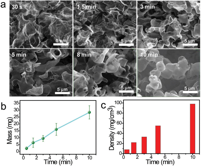
For the comparison with the graphene layers grown on Ni foams, we perform the growth of graphene layers on our 3D cross-linked Ni skeletons and commercial Ni foams in the same condition for 1.5 min at 1000°C, respectively (Fig. 3a,c). By contrast, 3D-GMOs show higher density of ~22 mg/cm3, which is one order of magnitude larger than that of Ni foam-grown graphene layers (~1 mg/cm3). The pore size of commercial Ni foam-grown graphene is 1–2 orders of magnitude larger than that of our porous cross-linked Ni-grown graphene (Fig. 3b,d). To explore the effect of growth time on the morphology and density of 3D-GMOs, we investigate the growth time ranging from 30 s to 10 min (Fig. 4a). We find that when the growth time is more than 3 min, there exist many graphite microspheres, and the more intact graphite microspheres are formed with the growth time increasing, suggesting the growth of graphene layers is highly efficient in such a short time. The morphology difference may be attributed to that when the growth time is shorter, the typical graphene layers wrapped on Ni particle skeletons are thinner and not strong enough to hold the “body” after the Ni skeletons being removed, resulting in the collapse of graphene layers. With prolonging the growth time, the graphene layers are thicker and stronger enough to avoid collapsing without the support of Ni skeletons, producing many graphite microspheres. Moreover, the density of 3D-GMOs increases linearly with the growth time. The higher density of 3D-GMOs of up to 100 mg/cm3 can be obtained when grown for 10 min (Fig. 4b,c).
Figure 3. Comparison between commercial Ni foam-grown graphene and our porous cross-linked Ni-grown graphene.
Ni foams are not removed (a) and removed (b). The porous Ni catalysts are not etched (c) and etched (d). The insets are the magnified images of (c) and (d), respectively. SEM images show that the pore size of commercial Ni foam-grown graphene is 1–2 orders of magnitude larger than that of our porous cross-linked Ni-grown graphene.
Figure 4. The effect of growth time on the morphology and density of 3D-GMOs.
(a) SEM images of the morphologies of 3D-GMOs at growth time of 30 s, 1.5 min, 3 min, 5 min, 8 min, 10 min, respectively. When the growth time is more than 3 min, there exist many graphite microspheres, and more intact graphite microspheres are formed with the growth time increasing. All the scale bars are 5 μm. (b) The mass of 3D-GMOs versus the growth time at 1000°C per 1.0 g Ni catalyst skeletons. (c) The density of 3D-GMOs increases nearly linearly with the growth time from 30 s to 10 min.
High-capacity removal of heavy metal ions
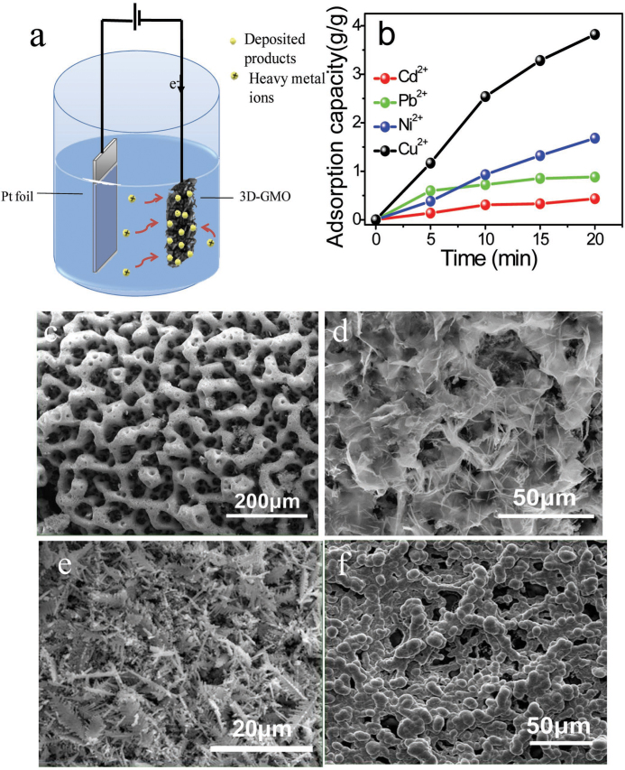
The 3D-GMOs as an electrode of the electrolytic deposition are investigated to remove heavy metal ions from aqueous solutions. The electric capture process of heavy metal ions is schematically illustrated in Figure 5a. We employ platinum (Pt) foils as anodes and free-standing 3D-GMOs as cathodes. Aqueous solutions containing single heavy metal ions (e.g. Cd2+, Pb2+, Cu2+, Ni2+) are used as electrolytes. Electrolytic deposition process is performed under a constant current of 0.05 A for 5 min, 10 min, 15 min and 20 min, respectively, and the final concentrations of the single heavy metal ions mentioned above in the aqueous solutions are measured by inductively coupled plasma atomic emission spectrometry (ICP-AES). As shown in Figure 5b, the adsorption capacities of 3D-GMOs increase with deposition time (Supplementary Fig. S3a–d). After 20-min deposition, the adsorption capacities are 434 mg/g, 882 mg/g, 1,683 mg/g and 3,820 mg/g corresponding to Cd2+, Pb2+, Ni2+ and Cu2+, respectively, which are much higher than that of the reported typical results using active carbon-based materials as adsorbents24,25,26,27. In addition, these values are higher than those of the reported graphene based adsorbents: 106.3 mg/g and 145.48 mg/g for Cd(II)33,36, 479 mg/g and 842 mg/g for Pb (II)31,40, 46.55 mg/g for Ni (II)43, 130 mg/g and 46.6 mg/g for Cu (II)34,35 (Supplementary Table S1) Interestingly, the deposited products on 3D-GMOs for 20 min show 3D porous structures derived from the 3D-GMOs templates in Figure 5c–f characterized by SEM (Supplementary Fig. S4), and the deposited products of Cd2+, Pb2+, Ni2+ and Cu2+are Cd(OH)2, PbO, Ni and Cu/Cu2O, respectively, determined by X-ray diffraction (XRD) patterns and energy dispersive X-ray (EDX) spectra (Supplementary Figs. S5–S8). We speculate that the high adsorption capacities for heavy metal ions originate from the following reasons. Firstly, the honeycomb-like 3D-GMOs provide the large-area templates for the deposited products of the metal ions, which continuously offer the 3D porous templates for the subsequent electrolytic deposition (Supplementary Fig. S3c–g). Secondly, the high conductivity of 3D-GMOs could enable the high electrolytic deposition rate. Lastly, the high density and effectively cross-linked structure of graphene layers sustain the free-standing monoliths and protect them from collapsing during the deposition process. Further, to investigate recovery performance of the 3D-GMOs, a desorption process is performed. In terms of the desorption of the deposited product of Cd2+, the free-standing 3D-GMO (deposited for 20 min) and the Pt foil are the anode and the cathode, respectively. A high concentration of 1.0 g/L (pH = 2.0) Cd (NO3)2 aqueous solution is electrolyte. After a constant current of 0.1 A applied for 1 min between the two electrodes, the deposited products on the 3D-GMO almost disappear (a desorption efficiency >96%) (Supplementary Fig. S9).
Figure 5. Electrolytic deposition on 3D-GMOs removing heavy metal ions.
(a) Schematic illustrations of the electrolytic deposition on 3D-GMOs removing heavy metal ions. (b) Typical adsorption capacity of 3D-GMOs versus time for the various heavy metals ions, Cd2+ (red line), Pb2+ (green line), Ni2+ (blue line) and Cu2+ (black line). SEM images of the deposited products of Cd2+ (c), Pb2+ (d), Cu2+ (e) and Ni2+ (f) on 3D-GMOs for the same deposition time of 20 min, showing 3D porous structures derived from the 3D-GMOs templates.
Discussion
Among the previous reports on synthesis of 3D graphene layers by CVD, the rapid preparation method of high-density 3D-GMOs is lack. We develop a highly efficient growth process to obtain high-density 3D-GMOs due to the prepared 3D cross-linked catalysts with high gas penetration and high catalytic reactivity. The large specific surface area, high conductivity and robust 3D structure are responsible for the ultra-high electrical adsorption capacities of 3D-GMOs.
Taking account of the drawback that Ni2+ generated by etching Ni skeletons with FeCl3/HCl solution makes water polluted, HCl solution as an alternative etchant for the recycled use of NiCl2 can resolve this problem. We demonstrate to etch the Ni templates with 3 M HCl solution, and the resulting NiCl2 solution is converted to catalyst templates again for further preparation of 3D-GMOs (Supplementary Fig. S10).
In conclusion, we fabricate the high-density 3D-GMOs by a rapid CVD strategy under atmospheric pressure, and demonstrate the high-capacity removal of heavy metal ions of the free-standing 3D-GMOs. The 3D-GMOs with high conductivity (~12 S/cm) and large specific surface area (~560 m2/g) have been achieved by CVD on 3D cross-linked Ni skeletons. The 3D-GMOs are firstly employed to speedily remove heavy metal ions with the high electric adsorption capacities and the fast desorption. The high density and effectively cross-linked structure ensure that 3D-GMOs remain their self supporting formation instead of collapsing even enduring electrolytic deposition of heavy metal ions. The new high-density 3D-GMOs with the outstanding properties fabricated by this highly efficient CVD technique have significant potential applications for the removal of heavy metal ions and the other promising areas including energy-storage devices, sensors, thermally conductive media, catalyst supports, and composites and so on.
Methods
Preparation of 3D-GMOs by CVD method
NiCl2·6H2O powders loaded in quartz boat were laid in the center of quartz tube furnace and annealed at 600°C under 100 sccm Ar and 200 sccm H2 for 10 min. After the reduction, the porous 3D Ni skeletons were formed. The growth process was employed under the gas flow of CH4 (30 sccm), Ar (200 sccm) and H2 (200 sccm) within the temperature range of 700 to 1000°C for the growth time from 30 s to 10 min. Subsequently, the quartz tube was taken out of furnace and cooled down to room temperature. After removing Ni templates by 1.0 M FeCl3/0.2 M HCl, the samples were repeatedly washed in water. Finally, the free-standing 3D-GMOs were obtained by the freezing dry.
Transmission electron microscopy
TEM and HRTEM imaging and electron diffraction were performed on a FEI Tecnai G2 F20 S-Twin microscope operated at an accelerating voltage of 200 kV. The TEM samples were prepared by sonicating at 1000 W for ~30 min, and 10 μL supernatant was dropped onto a microgrid.
Scanning electron microscopy
SEM images were obtained with a field emission gun scanning electron microscope (Quanta 400 FEG FEI) at an accelerating voltage of 20 kV. The SEM images were taken by depositing the samples onto the Si/SiO2 substrates.
Raman spectroscopy
Raman measurements were carried out using a Labram HR800 UV-NIR from Jobin Yvon with a laser wavelength of 633 nm. Raman spectra of the 3D-GMOs were taken by depositing the samples on glass slides.
Electrical conductivity
The electrical conductivity of 3D-GMOs was measured by a two-probe method. Firstly, the 3D-GMO was cut into a rectangular monolith, and two probes connected to Agilent B1500A were pressed on both ends of the 3D-GMO covered with silver paste, respectively.
The electrolytic deposition removing heavy metal ions
The electrolytic deposition process was employed in a two-electrode system. Platinum (Pt) foils and the free-standing 3D-GMOs were employed as cathodes and anodes, respectively. The joint point of 3D-GMOs and connected toothless alligator clips were covered by epoxy resin to protect the alligator clip from corrosion. 0.1 g/L Cd (NO3)2, 0.1 g/L Pb (NO3)2, 1.0 g/L NiSO4 and 1.0 g/L CuCl2 aqueous solutions (pH = 2.0) were used as electrolytes, respectively. The desorption process was similar to the adsorption process, except that a reversed constant current of −0.1 A and a high concentration electrolyte of 1.0 g/L (pH = 2.0) heavy metal ions were used.
Adsorption capacity
The final concentrations after electrolytic deposition were obtained using ICP-AES (Optima 2100 DV). The adsorption capacity qt (mg/g) after the electrolytic deposition for different time was calculated by the equation:  where C0 is the initial concentration and Ct is the final concentration after electrolytic deposition for different time. V is the volume of the solution and m is the mass of the freestanding 3D-GMOs.
Author Contributions
L. L. and W. L. designed the experiments and co-wrote the paper. W. L. and S. G. carried out the sample preparation, characterizations. L. W. and S. Q. assisted with implementing electrolytic deposition. Yu. G., X. G., M. C., S. L., C. Z., Y. G., M. L., J. X., X. W. and M. S. conducted the measurement experiments and data analysis. All authors discussed the results and commented on the manuscript.
Supplementary Material
Supplementary Information
Acknowledgments
This work was supported by the National Natural Science Foundation of China (Grant Nos. 10834004, 51102273), the Project of Chinese Academy of Sciences (KGZD-EW-303), Ministry of National Science and Technology Projects of China (Grants Nos. 2010CB934700, 2012CB722708). Prof. L. W. Liu thanks the Platforms of Characterization & Test and Nanofabrication Facility at Sinano for experimental assistance.
References
- Park S. & Ruoff R. S. Chemical methods for the production of graphenes. Nat. Nanotechnol. 4, 217–224 (2009). [DOI] [PubMed] [Google Scholar]
- Bae S. et al. Roll-to-roll production of 30-inch graphene films for transparent electrodes. Nat. Nanotechnol. 5, 574–578 (2010). [DOI] [PubMed] [Google Scholar]
- Dreyer D. R., Park S., Bielawski C. W. & Ruoff R. S. The chemistry of graphene oxide. Chem. Soc. Rev. 39, 228–240 (2010). [DOI] [PubMed] [Google Scholar]
- Li W. W. et al. Reduced graphene oxide electrically contacted graphene sensor for highly sensitive nitric oxide detection. ACS Nano 5, 6955–6961 (2011). [DOI] [PubMed] [Google Scholar]
- Zhu Y. W. et al. Carbon-based supercapacitors produced by activation of graphene. Science 332, 1537–1541 (2011). [DOI] [PubMed] [Google Scholar]
- Huang X., Qi X. Y., Boey F. & Zhang H. Graphene-based composites. Chem. Soc. Rev. 41, 666–686 (2012). [DOI] [PubMed] [Google Scholar]
- Huang X. et al. Graphene-based materials: synthesis, characterization, properties, and applications. Small 7, 1876–1902 (2011). [DOI] [PubMed] [Google Scholar]
- Huang X., Zeng Z. Y., Fan Z. X., Liu J. Q. & Zhang H. Graphene-based electrodes. Adv. Mater. 24, 5979–6004 (2012). [DOI] [PubMed] [Google Scholar]
- He Q. Y., Wu S. X., Yin Z. Y. & Zhang H. Graphene-based electronic sensors. Chem. Sci. 3, 1764–1772 (2012). [Google Scholar]
- Qi X. Y., Tan C. L., Wei J. & Zhang H. Synthesis of graphene-conjugated polymer nanocomposites for electronic device applications. Nanoscale 5, 1440–1451 (2013). [DOI] [PubMed] [Google Scholar]
- Eda G., Fanchini G. & Chhowalla M. Large-area ultrathin films of reduced graphene oxide as a transparent and flexible electronic material. Nat. Nanotechnol. 3, 270–274 (2008). [DOI] [PubMed] [Google Scholar]
- Yu Q. K. et al. Graphene segregated on Ni surfaces and transferred to insulators. Appl. Phys. Lett. 93, 113103 (2008). [Google Scholar]
- Kim K. S. et al. Large-scale pattern growth of graphene films for stretchable transparent electrodes. Nature 457, 706–710 (2009). [DOI] [PubMed] [Google Scholar]
- Li X. S. et al. Large-area synthesis of high-quality and uniform graphene films on copper foils. Science, 324, 1312–1314 (2009). [DOI] [PubMed] [Google Scholar]
- Chen Z. P. et al. Three-dimensional flexible and conductive interconnected graphene networks grown by chemical vapour deposition. Nat. Mater. 10, 424–428 (2011). [DOI] [PubMed] [Google Scholar]
- Schaedler T. A. et al. Ultralight metallic microlattices. Science 334, 962–965 (2011). [DOI] [PubMed] [Google Scholar]
- Mecklenburg M. et al. Aerographite: Ultra lightweight, flexible nanowall, carbon microtube material with outstanding mechanical performance. Adv. Mater. 24, 3486–3490 (2012). [DOI] [PubMed] [Google Scholar]
- Choi B. G., Yang M., Hong W. H., Choi J. W. & Huh Y. S. 3D macroporous graphene frameworks for supercapacitors with high energy and power densities. ACS Nano 6, 4020–4028 (2012). [DOI] [PubMed] [Google Scholar]
- Dong X. C. et al. 3D graphene-cobalt oxide electrode for high-performance supercapacitor and enzymeless glucose detection. ACS Nano 6, 3206–3213 (2012). [DOI] [PubMed] [Google Scholar]
- Cao X. H. et al. Preparation of Novel 3D graphene networks for supercapacitor applications. Small 7, 3163–3169 (2011). [DOI] [PubMed] [Google Scholar]
- Ji H. X. et al. Ultrathin graphite foam: a three-dimensional conductive network for battery electrodes. Nano Lett. 12, 2446–2451 (2012). [DOI] [PubMed] [Google Scholar]
- Shan C. S., Tang H., Wong T. L., He L. F. & Lee S. T. Facile Synthesis of a large quantity of graphene by chemical vapor deposition: an advanced catalyst carrier. Adv. Mater. 24, 2491–2495 (2012). [DOI] [PubMed] [Google Scholar]
- Lee J. S., Ahn H. J., Yoon J. C. & Jang J. H. Three-dimensional nano-foam of few-layer graphene grown by CVD for DSSC. Phys. Chem. Chem. Phys. 14, 7938–7943 (2012). [DOI] [PubMed] [Google Scholar]
- Mouni L., Merabet D., Bouzaza A. & Belkhiri L. Adsorption of Pb (II) from aqueous solutions using activated carbon developed from Apricot stone. Desalination 276, 148–153 (2011). [Google Scholar]
- Kobya M., Demirbas E., Senturk E. & Ince M. Adsorption of heavy metal ions from aqueous solutions by activated carbon prepared from apricot stone. Bioresour. Technol. 96, 1518–1521 (2005). [DOI] [PubMed] [Google Scholar]
- Anirudhan T. S. & Sreekumari S. S. Adsorptive removal of heavy metal ions from industrial effluents using activated carbon derived from waste coconut buttons. J. Environ. Sci. 23, 1989–1998 (2011). [DOI] [PubMed] [Google Scholar]
- Karnitz O. Jr et al. Adsorption of heavy metal ion from aqueous single metal solution by chemically modified sugarcane bagasse. Bioresour. Technol. 98, 1291–1297 (2007). [DOI] [PubMed] [Google Scholar]
- Bhunia P., Kim G., Baik C. & Lee H. A strategically designed porous iron-iron oxide matrix on graphene for heavy metal adsorption. Chem. Commun. 48, 9888–9890 (2012). [DOI] [PubMed] [Google Scholar]
- Chandra V. et al. Water-dispersible magnetite-reduced graphene oxide composites for arsenic removal. ACS Nano 4, 3979–3986 (2010). [DOI] [PubMed] [Google Scholar]
- Kemp K. C. et al. Environmental applications using graphene composites: water remediation and gas adsorption. Nanoscale 5, 3149–3171 (2013). [DOI] [PubMed] [Google Scholar]
- Madadrang C. J. et al. Adsorption behavior of EDTA-graphene oxide for Pb (II) removal. ACS Appl. Mater. Interfaces 4, 1186–1193 (2012). [DOI] [PubMed] [Google Scholar]
- Sui Z. Y., Meng Q. H., Zhang X. T., Ma R. & Cao B. Green synthesis of carbon nanotube-graphene hybrid aerogels and their use as versatile agents for water purification. J. Mater. Chem. 22, 8767–8771 (2012). [Google Scholar]
- Zhao G. X., Li J. X., Ren X. M., Chen C. L. & Wang X. K. Few-layered graphene oxide nanosheets as superior sorbents for heavy metal ion pollution management. Environ. Sci. Technol. 45, 10454–10462 (2011). [DOI] [PubMed] [Google Scholar]
- Yang S. T. et al. Folding/aggregation of graphene oxide and its application in Cu2+ removal. J. Colloid Interface Sci. 351, 122–127 (2010). [DOI] [PubMed] [Google Scholar]
- Zhang N. N., Qiu H. X., Si Y. M., Wang W. & Gao J. P. Fabrication of highly porous biodegradable monoliths strengthened by graphene oxide and their adsorption of metal ions. Carbon 49, 827–837 (2011). [Google Scholar]
- Gao H. C., Sun Y. M., Zhou J. J., Xu R. & Duan H. W. Mussel-inspired synthesis of polydopamine-functionalized graphene hydrogel as reusable adsorbents for water purification. ACS Appl. Mater. Interfaces 5, 425–432 (2013). [DOI] [PubMed] [Google Scholar]
- Deng X. J., Lu L. L., Li H. W. & Luo F. The adsorption properties of Pb (II) and Cd (II) on functionalized graphene prepared by electrolysis method. J. Hazard. Mater. 183, 923–930 (2010). [DOI] [PubMed] [Google Scholar]
- Cong H. P., Ren X. C., Wang P. & Yu S. H. Macroscopic multifunctional graphene-based hydrogels and aerogels by a metal ion induced self-assembly process. ACS Nano 6, 2693–2703 (2012). [DOI] [PubMed] [Google Scholar]
- Huang Z. H. et al. Adsorption of lead (II) ions from aqueous solution on low-temperature exfoliated graphene nanosheets. Langmuir 27, 7558–7562 (2011). [DOI] [PubMed] [Google Scholar]
- Zhao G. X. et al. Removal of Pb (II) ions from aqueous solutions on few-layered graphene oxide nanosheets. Dalton Trans. 40, 10945–10952 (2011). [DOI] [PubMed] [Google Scholar]
- Lee Y. C. & Yang J. W. Self-assembled flower-like TiO2 on exfoliated graphite oxide for heavy metal removal. J. Ind. and Eng. Chem. 18, 1178–1185 (2012). [Google Scholar]
- Li J. et al. Removal of Cu (II) and fulvic acid by graphene oxide nanosheets decorated with Fe3O4 nanoparticles. ACS Appl. Mater. Interfaces 4, 4991–5000 (2012). [DOI] [PubMed] [Google Scholar]
- Ren Y. M. et al. Graphene/δ-MnO2 composite as adsorbent for the removal of nickel ions from wastewater. Chem. Eng. J. 175, 1–7 (2011). [Google Scholar]
- Chandra V. & Kim K. S. Highly selective adsorption of Hg2+ by a polypyrrole- reduced graphene oxide composite. Chem. Commun. 47, 3942–3944 (2011). [DOI] [PubMed] [Google Scholar]
- Georgakilas V. et al. Functionalization of graphene: covalent and non-covalent approaches, derivatives and applications. Chem. Rev. 112, 6156–6214 (2012). [DOI] [PubMed] [Google Scholar]
- Gong Y. P. et al. Layer-controlled and wafer-scale synthesis of uniform and high-quality graphene films on a polycrystalline nickel catalyst. Adv. Funct. Mater. 22, 3153–3159 (2012). [Google Scholar]
Associated Data
This section collects any data citations, data availability statements, or supplementary materials included in this article.
Supplementary Materials
Supplementary Information


