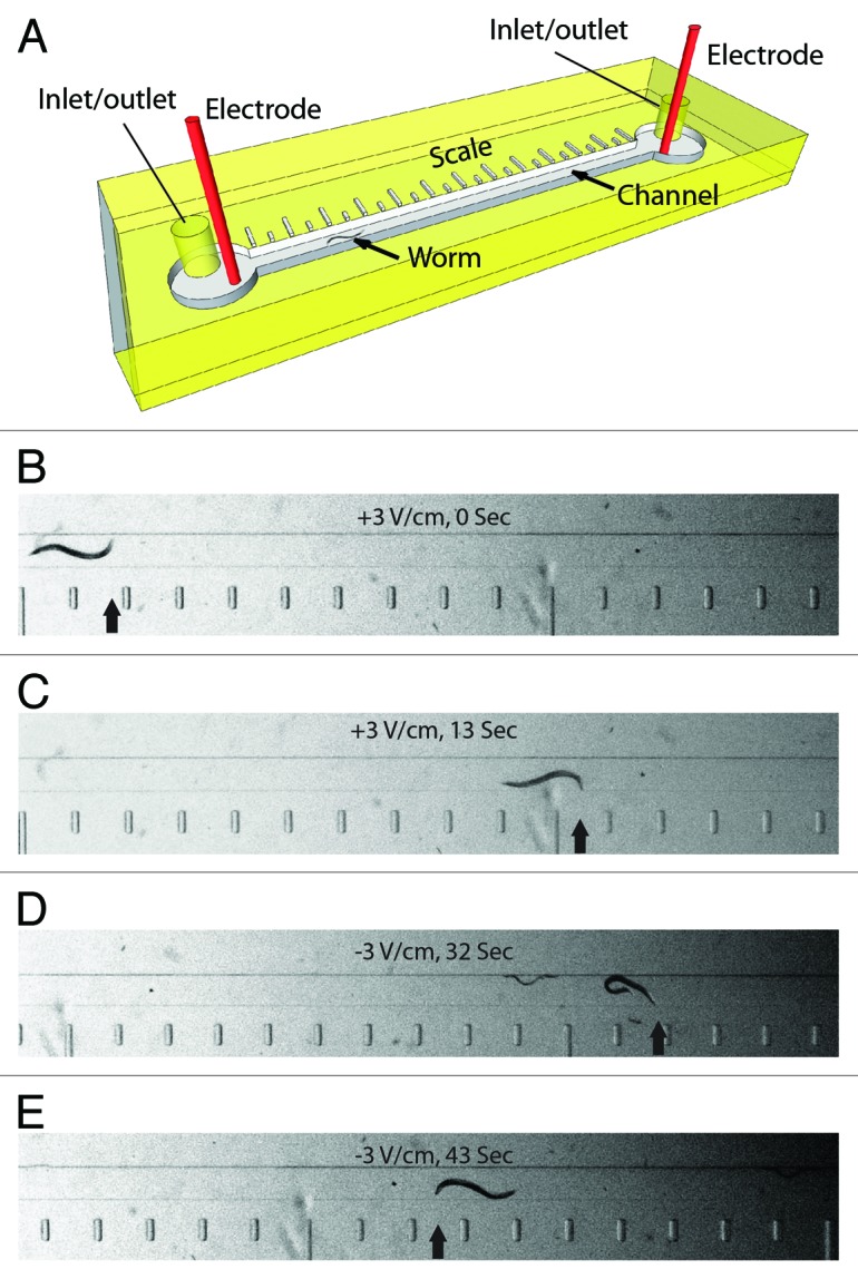
Figure 1. Microfluidic electrotaxis setup. (A) A detailed view of the microfluidic device. Worms are loaded and removed through inlet/outlet tubes. Electrotaxis is performed in the channel (a worm is shown). The scale along the length of the channel is used to determine the speed. (B‒E) Snapshots of a worm in the channel during electrotaxis. Scale bar is visible on the bottom. The electric field voltage and time are shown in each panel. The head of the worm is marked by an arrow. Reversal of the electric field polarity (D and E) causes the worm to switch its direction of motion.
