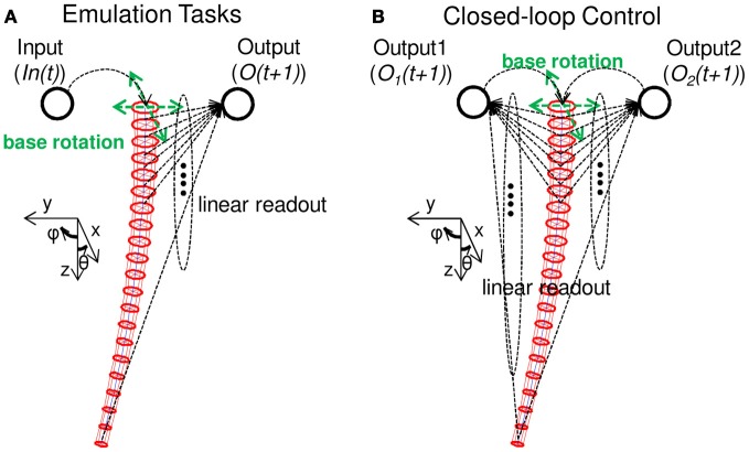
Figure 3.
Schematics explaining the tasks adopted in this paper. (A) Schematics showing the nonlinear dynamical system emulation tasks (Task 1). An input (In(t)) is projected as a base rotation angle, and accordingly, the soft robotic arm shows passive body dynamics. By setting a linear readout for each longitudinal spring length in each compartment, an output (O(t + 1)) is calculated as a weighted sum of all the spring lengths. By adjusting only the linear readout, we demonstrate whether the system can emulate complex nonlinear dynamical systems. (B) Schematics showing the implementation of closed-loop control (Task 2). Similar to Task 1, by adjusting the linear readouts, two variables of a nonlinear limit cycle are emulated and fed back as the next input to the system to generate the base rotation movement. Accordingly, the nonlinear limit cycle is embedded onto the arm in a closed-loop manner. See the text for details.

