
Figure 9.
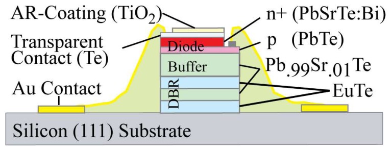
Detailed schematic representation of the detector part layout as shown in the lower part of Figure 1, including the Distributed Bragg Reflector (DBR), the buffer layer and the photosensitive diode.
Official websites use .gov
A
.gov website belongs to an official
government organization in the United States.
Secure .gov websites use HTTPS
A lock (
) or https:// means you've safely
connected to the .gov website. Share sensitive
information only on official, secure websites.
Detailed schematic representation of the detector part layout as shown in the lower part of Figure 1, including the Distributed Bragg Reflector (DBR), the buffer layer and the photosensitive diode.