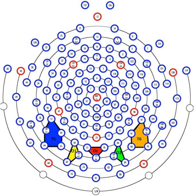
Figure 2.
Virtual electrodes approximating the 10–20 system were created by averaging over groups of electrodes. The colored polygons show the five most posterior electrode groupings and roughly correspond to T5 (10–20 system; P7 in the 10–10 system; blue), O1 (yellow), Oz (red), O2 (green), and T6 (10–20 system; P8 in the 10–10 system; orange).

