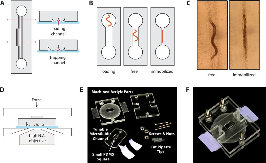
Figure 2.
Worm immobilization device. (A) Cross sections. A tunable-diameter microfluidic channel is formed by sealing an elastomer with cylindrical ridges onto a glass coverslip. The loading channels are narrower than the worm-trapping region to confine the worm in the middle of the device. (B) A worm is placed into one of the access ports and loaded by aspiration. The device is compressed to constrict the channel and immobilize the worm. (C) Microscope images of a worm in the device. An adult worm can be cultured for hours in an uncompressed channel and reversibly immobilized for imaging at specific time points. (D) An acrylic clamping rig maintains compression of the elastomer against the glass, while allowing microscope access for imaging through the coverslip. (E) The clamping rig includes slats to facilitate mounting on a microscope stage. A PDMS square (6 × 3 × 2 mm3) is placed over the microchannels to focus the compression force. (F) Assembled device.

