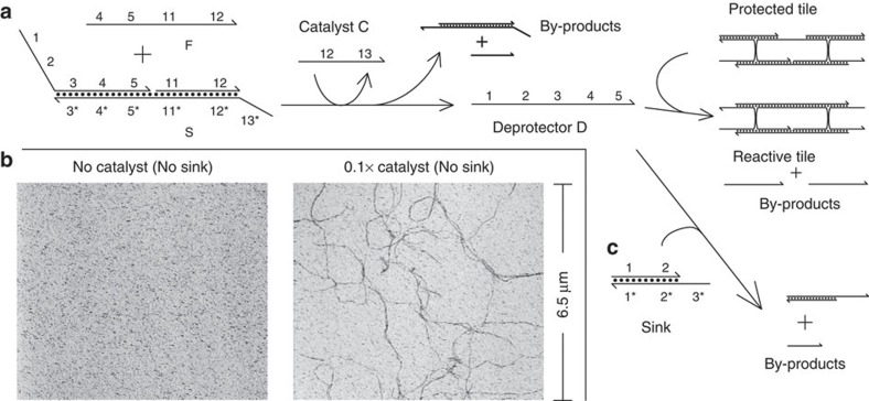
Figure 3. Upstream control circuit.
(a) A non-covalent catalytic system that produces the deprotector for method 3 as a product, based on the study by Zhang et al.27 The catalyst, an oligonucleotide with sequence independent of the deprotector, speeds up the strand-displacement reaction between reactants F and S to release of the deprotector. As part of the complex, the deprotector is mostly double-stranded and will not react with the protected tile. (b) AFM results on the integrated reaction network. The left panel shows the network in absence of catalyst (2-day reaction time), and the right panel shows the network in the presence of 20 nM catalyst (2 h reaction time). In both panels, the initial concentration of the protected tile was 200 nM, of F was 440 nM, of S was 220 nM. The concentration of the catalyst in the right panel was 20 nM, 0.1 × of the limiting reagent (protected tile). DNA nanotubes form in the presence of catalyst, and do not form in the absence of catalyst. (c) The sink complex serves as a competitive threshold for the deprotector to prevent small amounts of released deprotector from causing DNA nanotube assembly.

