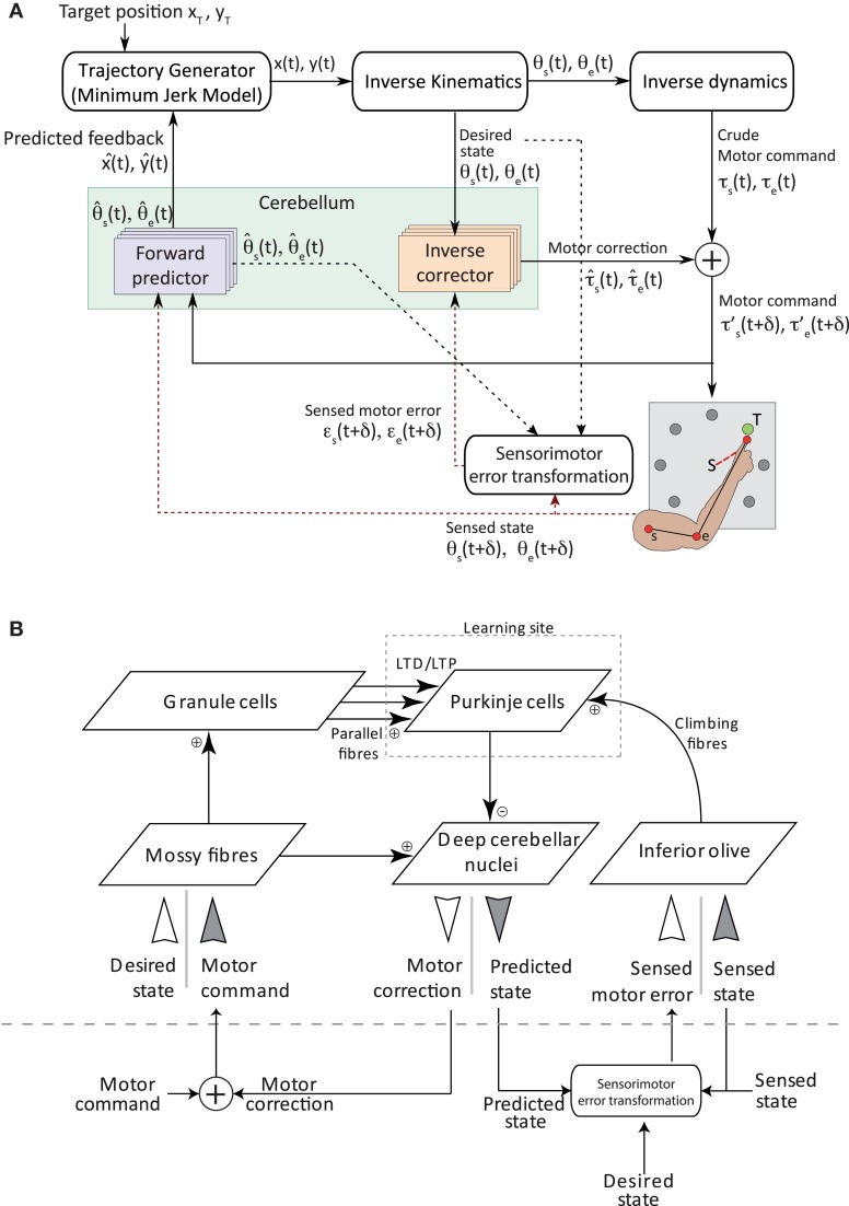
Figure 1.
Sensorimotor control architecture. (A) Overview of the integrated model for adaptive voluntary movements. An optimal controller computes a set of torque commands to generate smooth trajectories of the arm end-point (i.e., the “finger”) toward target positions. Desired states of both joints reach a set of four inverse cerebellar models, which estimate the corrective torques used to produce the final motor commands. The cerebellar forward model uses the motor command efference copy to predict the future state (position and speed) of the arm end-point and sends it to the high-level controller. Feedback signals include state information (i.e., the angular position and speed of each joint) as well as motor error information (i.e., the difference between desired and actual state of each joint). These signals (drawn in red dash) provide the basis to compute the teaching signals for both cerebellar internal models. The sensorimotor error module is responsible for transforming a sensory error—using desired, predicted and sensed state, represented in black and red dash line—into a motor error. Motor commands and feedback signals are algorithmically delayed (both by δ = 50 ms in the simulations presented here) to account for central↔peripheral transmission delays in biological systems. The execution of each trajectory takes 0.7 s followed by a 0.3 s refractory period, during which joint positions are reset and cerebellar neuronal activities return to baseline level. We also assume that high-level recalculations of the entire arm trajectories cannot be performed in the absence of forward model predictions. (B) Model cerebellar microcomplex circuit. Each box indicates a population of spiking neurons. The same cerebellar circuit implements both forward (dark gray inputs) and inverse (white inputs) internal models.

