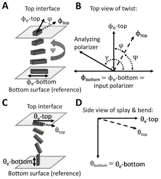
Figure 9.
Experimental set-ups and angle diagrams used to determine azimuthal (A and B) and zenithal (C and D) anchoring energies. (A) Schematic illustration of a twisted nematic LC (TNLC). (B) Diagram depicting the angles used to characterize the TNLC between two polarizers. The azimuthal orientation of the easy axis of the LC (defined by φ 3) and the azimuthal orientation of the LC director (defined by φ) are shown for both the top and bottom surfaces. Modified and reproduced with permission.14 (C–D) Schematic illustrations and corresponding definitions of angular displacements of the director in a LC film with planar-homeotropic hybrid anchoring conditions. The bottom surface is assumed to cause strong homeotropic anchoring and is used as a reference surface. The orientation of the easy axis of the LC at the top surface is characterized by the zenithal angle θ3, and the orientation of the LC director is characterized by θ.

