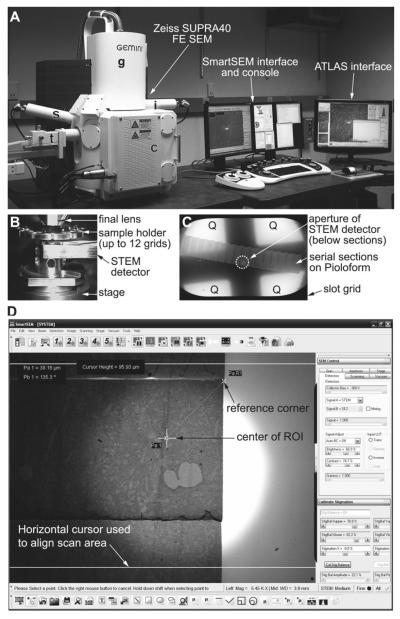
Fig. 3.
(a) Zeiss SUPRA 40 field emission scanning electron microscope is equipped with a secondary electron detector (s), an in-lens detector (i), and a retractable detector for transmitted electrons (STEM detector; t). The column (g) contains the gun assembly and objective lenses. The specimen chamber door (c) slides open outward with the stage. The SEM is controlled through the SmartSEM interface and console (keyboard and joysticks can be seen in front of the monitors), or the integrated ATLAS system for large-field imaging. (b) TV camera view of the specimen chamber showing the arrangement of the final lens, STEM detector, and sample holder clipped onto the stage. Working distance is 4–5 mm between the final lens and the specimen, as well as between the specimen and the detector. (c) Low-magnification STEM image of an entire slot grid containing serial sections. Below the sections, the aperture of the STEM detector can be seen (circle with dotted line), which must to be aligned to the center of the field. Four quadrants (Q) of the detector element are also used for imaging. Imaging mode (normal or inverted) can be set for each detector element on the SmartSEM interface. (d) A screenshot image of the SmartSEM interface, showing a low-magnification (×5,450) STEM image of serial sections. The interface has a variety of useful measurement and annotation tools, which are used to navigate to the ROI from the reference corner of each section. The bright circular area seen in the center of the field is the aperture of the STEM detector. The distance between the two horizontal cursor lines is about 96 μm.

