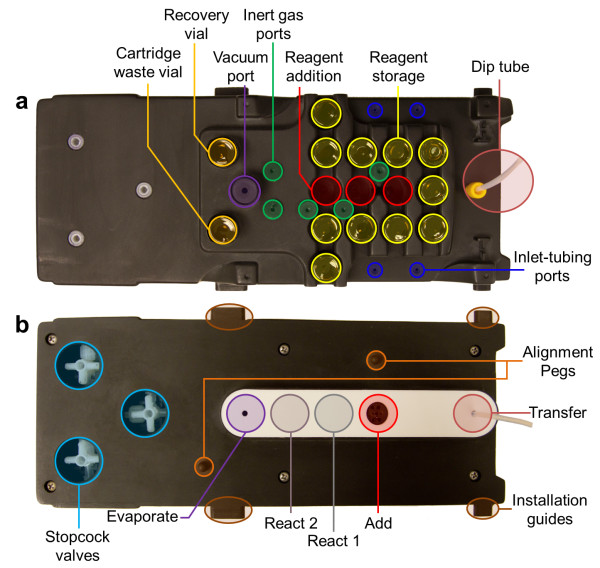
Figure 4.
Overview of the disposable cassette. (a) The top view of the disposable cassette illustrates the locations for reagent addition and storage along with gas ports for the gas supplier to provide vacuum and inert gas. Tubing extends out of the inlet-tubing ports for radioisotope and external additions. (b) Bottom view. The reactor seals against various positions on a PTFE-coated silicone gasket underneath the cassette to perform various unit operations (Evaporate, React, Add, and Transfer). Each cassette contains three stopcock valves and has a dip tube for transferring products to purification cartridges, subsequent cassettes, or the HPLC injection valve.

