
Fig. 1.
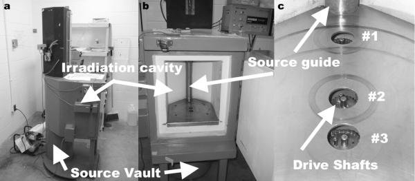
The Mark I-68A 137Cs irradiator is shown from the side demonstrating the location of the source vault in relationship to the irradiation cavity, (a). The source resides in the source vault while in the “off” position and moves up along the source guide, (b), into the “on” position to expose the irradiation cavity with gamma radiation. The manufacturer provided dose distribution mappings are delineated at three specific cross-sectional planes that correspond with three drive shafts used to rotate sample turntables, (c).