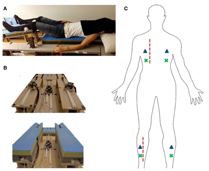
Figure 1.
Experimental setup. (A) Picture of experimental setup. Participant lying on robotic stroking device. (B) Robotic stoking device shown from feet perspective. Top: padding removed for motor view. Bottom: robot with padding as used in the experiment. (C) Schematic representation of stroking regions (dashed red line), tactile vibrators (blue triangles), and thermocouple placement (green x).

