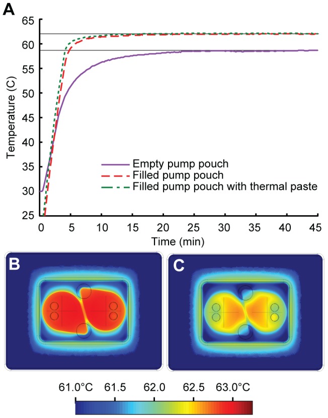
Figure 3. Thermal control within the cartridge.

(a) Measured temperature of the fluid inside the reaction pouch of a cartridge attached to the heater as a function of time. Filling the pump pouch with liquid improves the thermal transfer from the heater to the reaction fluid, which reaches a stable temperature of 62±0.1°C within approximately ten minutes. Thermal paste applied between the heater surface and pump pouch provides no further improvements. (b) and (c) Thermal simulations (Comsol Multiphysics) of the cartridge on top of the heater, showing horizontal cross-sections within the center of the reaction fluid layer of the cartridge. (b) Uniform heating to the desired temperature (63°C) is observed using a model with ideal thermal contact between cartridge and heater, with no air gap. (c) Introducing a 150 µm thick thermally-resistive layer between cartridge and heater leads to a lower temperature and less uniform heating within the reaction pouch. The cross-hatches in the middle of the pump pouches indicate the dimensions of the circular reaction pouches. An air bubble was intentionally introduced into the outlet port of the reaction chamber to simulate trapped air in the reaction pouches after fluid is inserted.
