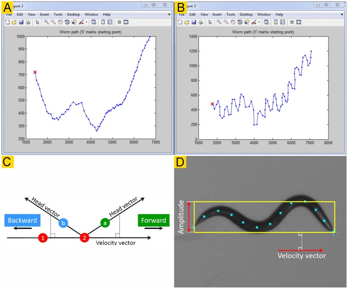
Figure 2. Reconstruction of travel path, and determination of movement direction and body amplitude.
A & B. The traveling paths of a wild-type worm reconstructed based on the positions of the centroid (A) and the nose/1st marker point (B). C. Directionality is determined by comparing the directions of a velocity vector and a head vector. The velocity vector is obtained by connecting the centroid positions of two consecutive frames (red circles “1” and “2”) whereas the head vector by connecting the current centroid and head positions. The green circle labeled “a” and the blue circle labeled “b” show that the head vector is projected to the positive and negative sides of the velocity vector, respectively. The worm is moving forward if the projection of the head vector onto the velocity vector is positive. D. The amplitude is determined by first finding the velocity vector, and then drawing a box in alignment with the velocity vector to enclose the widest points of the spline with the width of the box being the worm amplitude.

