
Fig. 3.
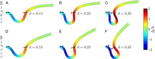
Demonstration of the counterbend effect on filament bundles for three horizontal displacements d, a sliding resistance  , and two basal constraints: internally anchored filaments at
  (welded bundle) (A–C) and filament bundles with no basal sliding resistance (D–F). The black arrows depict the actuation force required to hold the filament bundle at a given displacement d and the associated reaction force at the clamped base. The magnitude of this force was found to be
  for
for  in A–C and
  for
for  in D–F, respectively. Sliding deformations are represented by the internal connecting links, where the overlaid surface coloring indicates the sliding displacement distribution
  relative to the bundle diameter b.