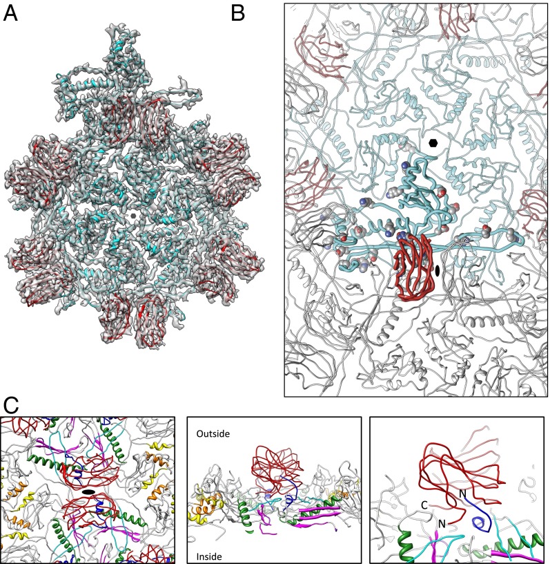
Fig. 4.
ε15 subunit interactions. (A) An asymmetric unit for ε15 consists of seven gp7 (cyan) and seven gp10 (red) subunits. For illustration purposes, additional gp10 subunits are highlighted to illustrate the dimeric relationship. (B) One gp10 (bold red subunit) and one gp7 (bold cyan subunit) are shown with potential salt bridges shown as spheres (Table S2). (C) The gp10 dimer is highlighted in red and spans the twofold axis (Left). Four gp7 subunits are directly below a single gp10. The N-arm regions of gp7 are colored in dark blue and flank the outer strands of gp7. The color annotations for gp7 are the same as defined in Fig. 2B. Directly below the gp10 dimers are the gp7 E-loops (cyan). Rotating 90° shows a slice through the capsid with both gp10 termini positioned at the twofold interface, protruding down into the gp7 subunits (Center). A zoomed-in view of this region highlights the positioning of the N-arm of gp7 and the termini of gp10 (Right).

