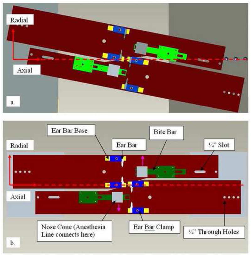
Fig. 2.

Layout of holder design in Pro/ENGINEER. a) Top view of dual rat configuration in IndyPET-II. b) Top view of configuration in microPET P4. The green structures are the bite-bars. The white, yellow and blue structures are the ear-bars, ear-bar supports and the clamps, respectively. Grey boxes are the anesthesia masks. Pink arrows on drawing (b) show exits from the masks to the anesthesia tubing. Horizontal dotted line indicates the main axis of the scanner bore.
